Launch and recovery ramp system

Active Publication Date: 2009-06-16
LOCKHEED MARTIN CORP
View PDF4 Cites 17 Cited by
  • Summary
  • Abstract
  • Description
  • Claims
  • Application Information

AI Technical Summary

Benefits of technology

[0006]A launch and recovery system for use by a host vessel in launching and recovering a sub-ordinate vessel includes a ramp structure that is connected to a host vessel and movable so that at least its remote or distal end can be placed in the water, preferably at the stern of the host vessel. The ramp includes interior portions thereof that can be selectively flooded to control the buoyancy of the ramp at its distal or remote end thereof to thus effect some measure of control of the inclination of the ramp. Additionally, one or more types of flow structures can be provided that effect control of the ramp as a function of water flow through and/or across the ramp. In one form, the flow structures can take the form of one or more thru-flow passages in the ramp so that water from the forward or leading side of the ramp can pass therethrough to the rearward or trailing side thereof. Various flow-control devices, such as moveab

Problems solved by technology

While the prior ramp-type systems have functioned relatively satisfactorily for their intended purposes, the prior systems are not well-suited for sub-ordinate vessel recovery at higher speeds since the effects of surface and/or sub-surface currents, waves, and wind action on the two vehicles oftentimes can ca

Method used


Image

  • Launch and recovery ramp system
  • Launch and recovery ramp system
  • Launch and recovery ramp system

Examples


Embodiment Construction

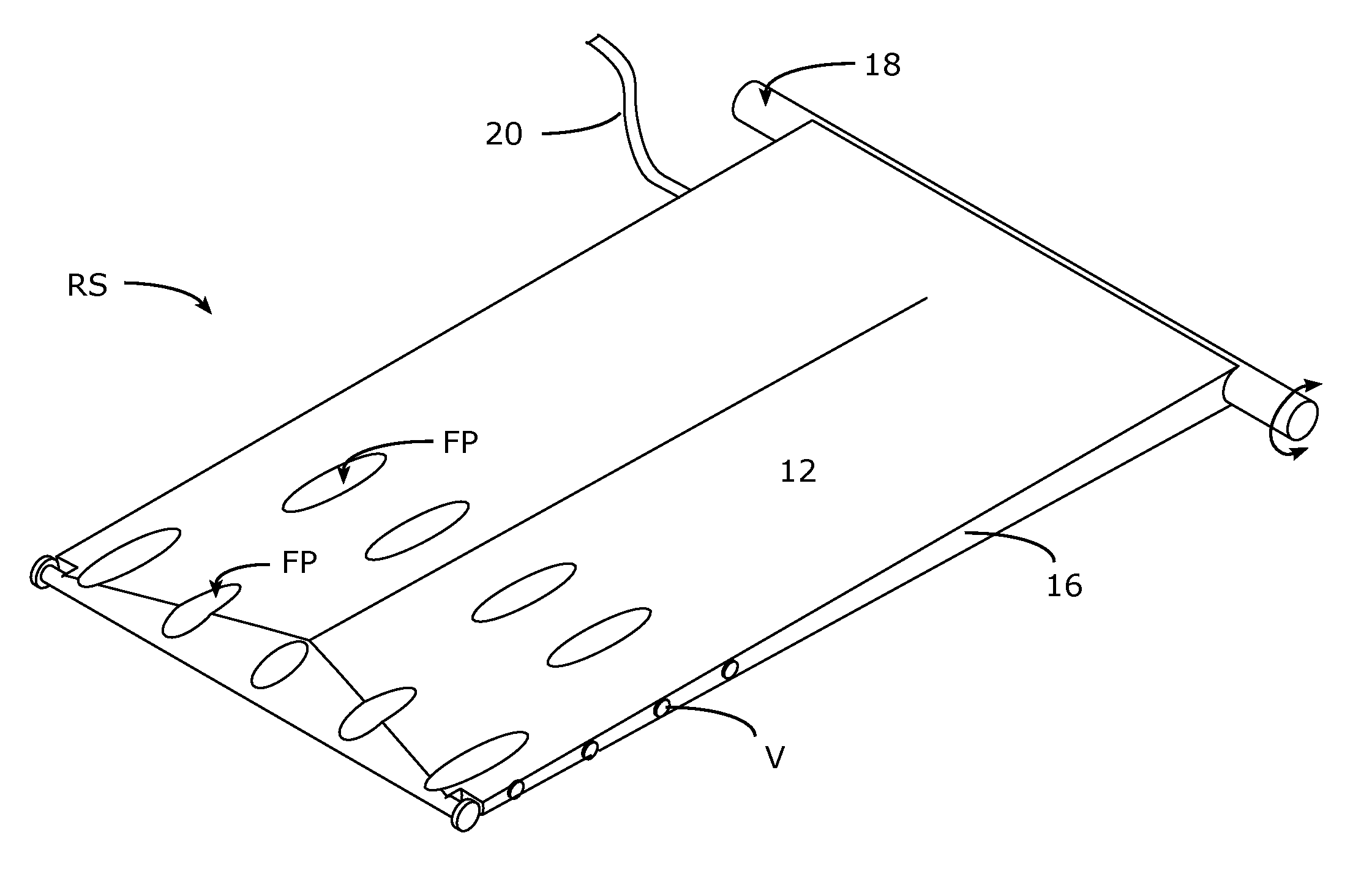
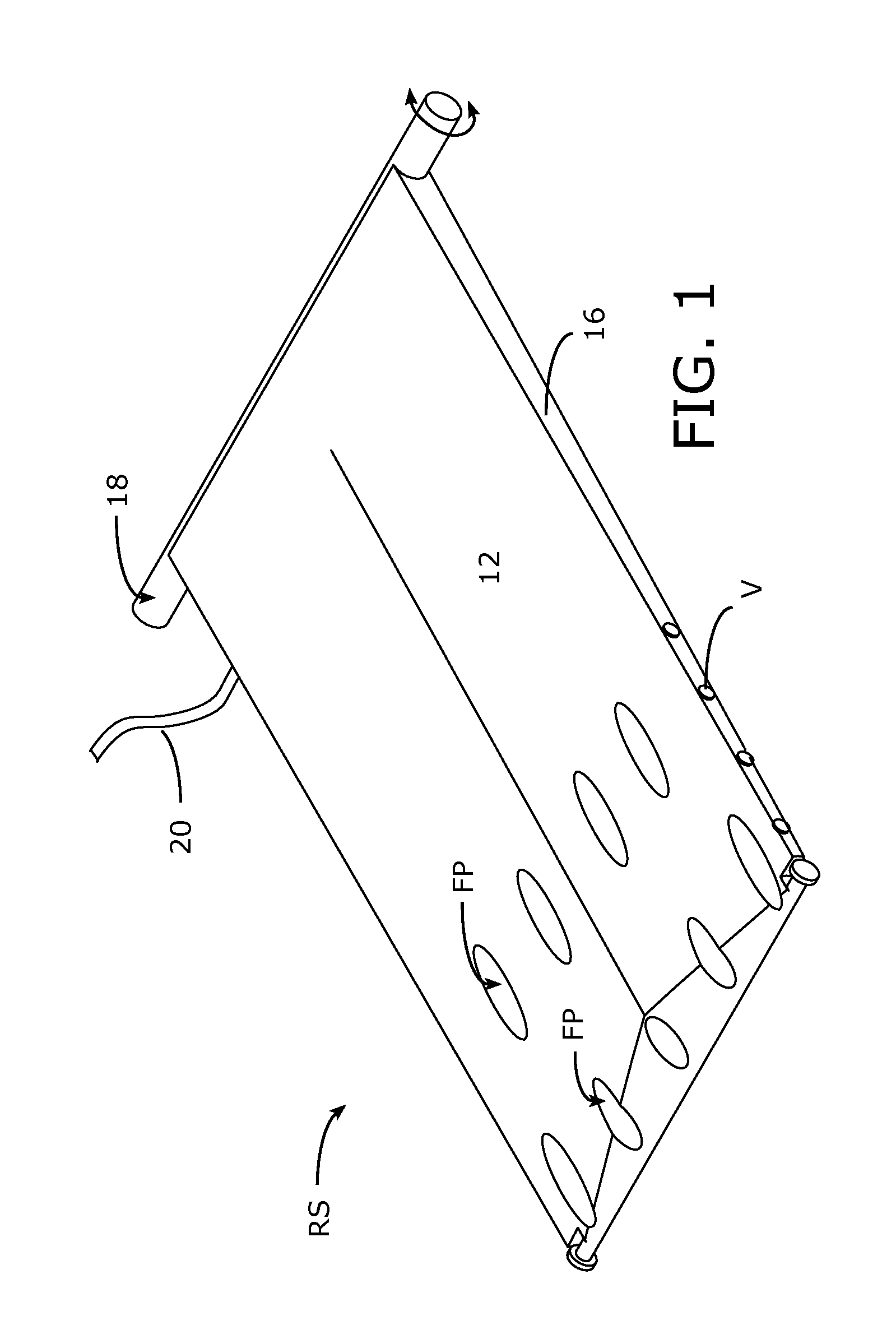
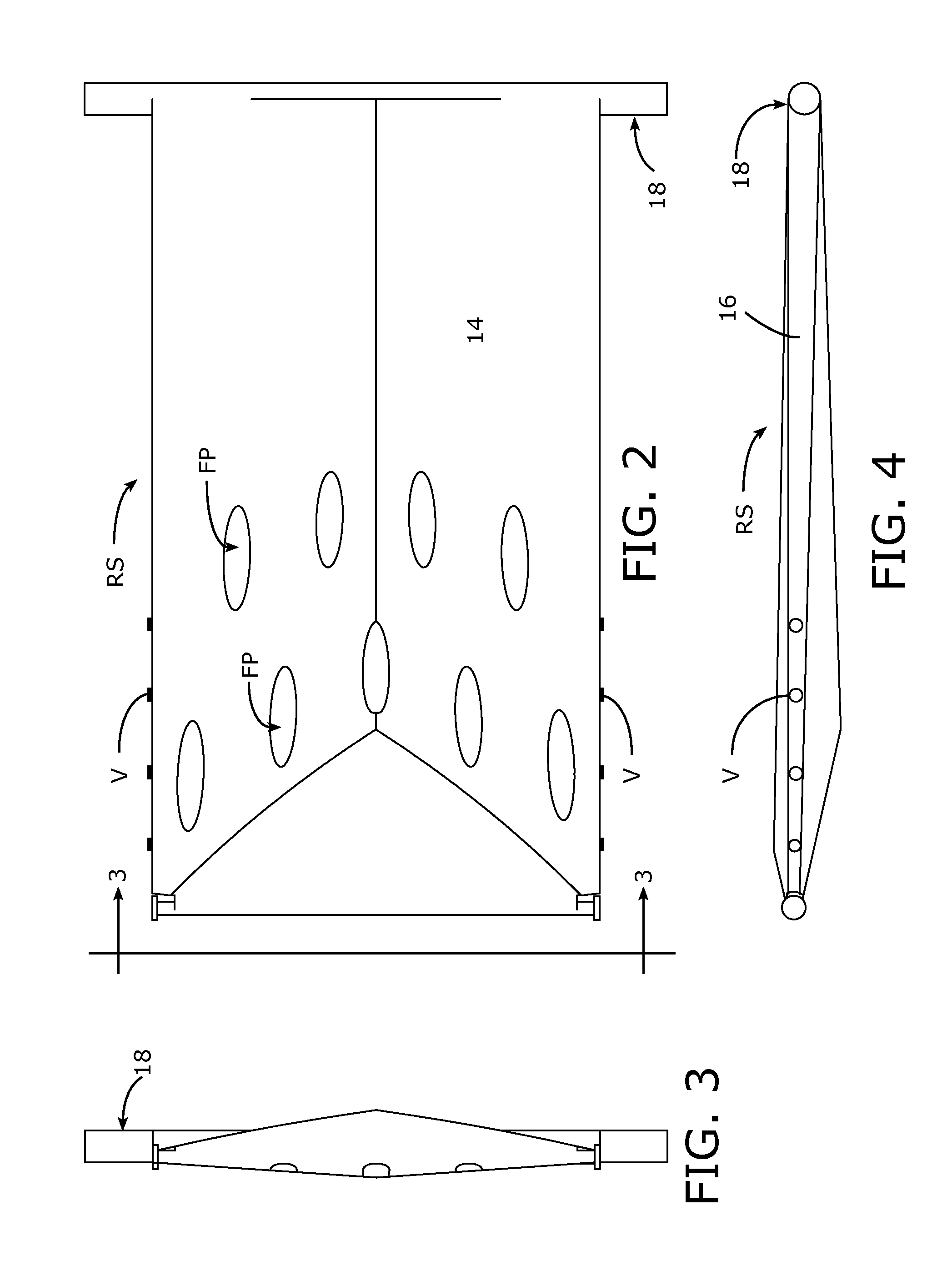
[0025]FIGS. 1-4 illustrate an example ramp structure in accordance with the present invention designated therein by the reference character RS. The ramp structure RS is typically formed as a weldment and includes a top side 12 (FIG. 1), a bottom side 14 (FIG. 2) and lateral sides 16. A shaft 18 or shaft-like equivalent is mounted at the forward end of the ramp structure 10 to allow a pivoting motion as explained below in relationship to FIG. 5; the shaft 18 is typically journalled in appropriate bearings or equivalent mounts on the host watercraft vessel. The top surface 12 need not be flat and can be formed from appropriately cut and shaped panels that are welded together. In a similar manner, the bottom surface 14 likewise need not be flat and can be formed from appropriately cut and shaped panels that are also welded together. The lateral sides 16 are welded to the top and bottom surfaces, 12 and 14, to form the structure shown. In general and except as described below, the ramp ...


PUM


Abstract

A launch and recovery system for use by host vessel in launching and recovering a sub-ordinate vessel includes a ramp structure that is connected to a host vessel and movable so that at least its remote or distal end can be placed in the water, preferably at the stern of the host vessel. The ramp includes interior portions thereof that can be selectively flooded to control the buoyancy of the ramp at least its distal or remote end thereof to thus effect some measure of control of the inclination of the ramp. Additionally, one or more types of flow structures can be provided that effect control of the ramp as a function of water flow through and/or across the ramp. In one form, the flow structures can take the form of one or more thru-flow passages in the ramp so that water from the forward or leading side of the ramp can pass therethrough to the rearward or trailing side thereof. Various flow-control devices, such as moveable plates, baffles, or other members are controlled to increase or decrease flow rate through the flow passages to control the relative pitch or inclination of the ramp. In another form, the flow structures can take of the form of a movable fin or plane connected to the ramp structure that can be adjusted, either manually and/or as part of a control system, to control the relative pitch or inclination of the ramp.

Description

CROSS-REFERENCE TO RELATED PATENT APPLICATION[0001]This application claims the benefit of commonly owned U.S. Provisional Patent Application 60 / 791,210 filed Apr. 12, 2006 by the applicant herein, the disclosure of which is incorporated herein by reference.[0002]The subject matter of this application is related to that disclosed in commonly owned patent application Ser. No. 11 / 685,886 filed Mar. 14, 2007 by the inventor herein and entitled “Sub-Ordinate Vehicle Recovery / Launch System,” the disclosure of which is incorporated herein by reference.BACKGROUND OF THE INVENTION[0003]The present invention relates to apparatus and method for the launching and the recovery of a sub-ordinate vehicle by host vehicle and, more particularly, to the launching and recovery of sub-ordinate seaborne surface and / or sub-surface vessels by a host seaborne surface and / or sub-surface vessel.[0004]Various seaborne systems are known by which a host vessel can launch a sub-ordinate vessel and by which the h...

Claims


Application Information

Patent Timeline
IPC IPC(8): B63B35/40
CPCB63B23/32
Inventor SAID, BRIAN R.
Owner LOCKHEED MARTIN CORP
Why Eureka
Try Eureka