Brush chipper with improved feed rollers

a technology of feed rollers and chippers, which is applied in the field of improved feed roller systems, can solve the problems that the cleats or ribs of the prior art have not provided remedy for observed bucking, and achieve the effect of reducing the chance of bucking and reducing the occurrence of bucking

a technology of feed rollers and chippers, which is applied in the field of improved feed roller systems, can solve the problems that the cleats or ribs of the prior art have not provided remedy for observed bucking, and achieve the effect of reducing the chance of bucking and reducing the occurrence of bucking

US7546964B2Active Publication Date: 2009-06-16VERMEER MFG CO

Image

  • Brush chipper with improved feed rollers
  • Brush chipper with improved feed rollers
  • Brush chipper with improved feed rollers

Examples


Embodiment Construction

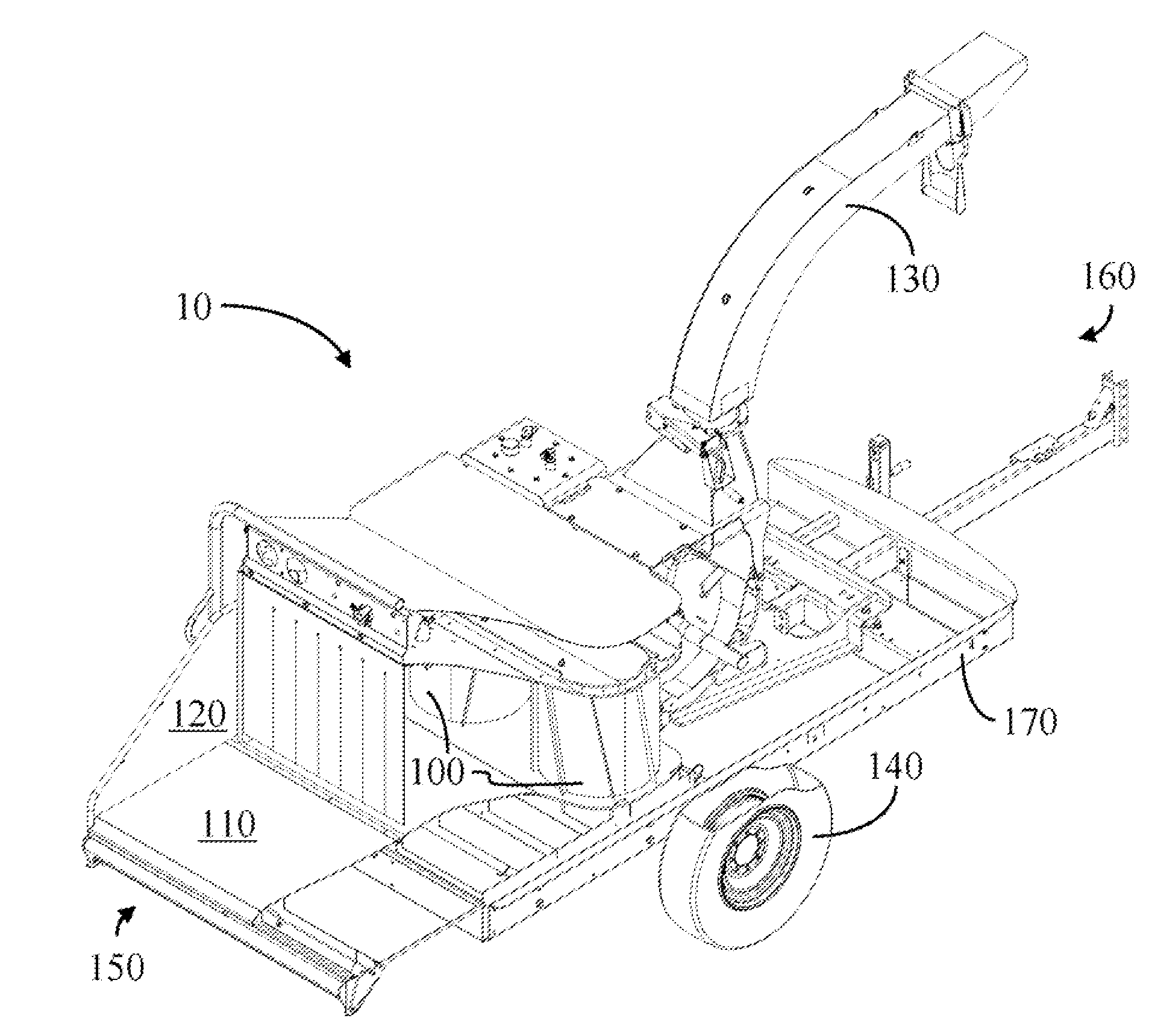
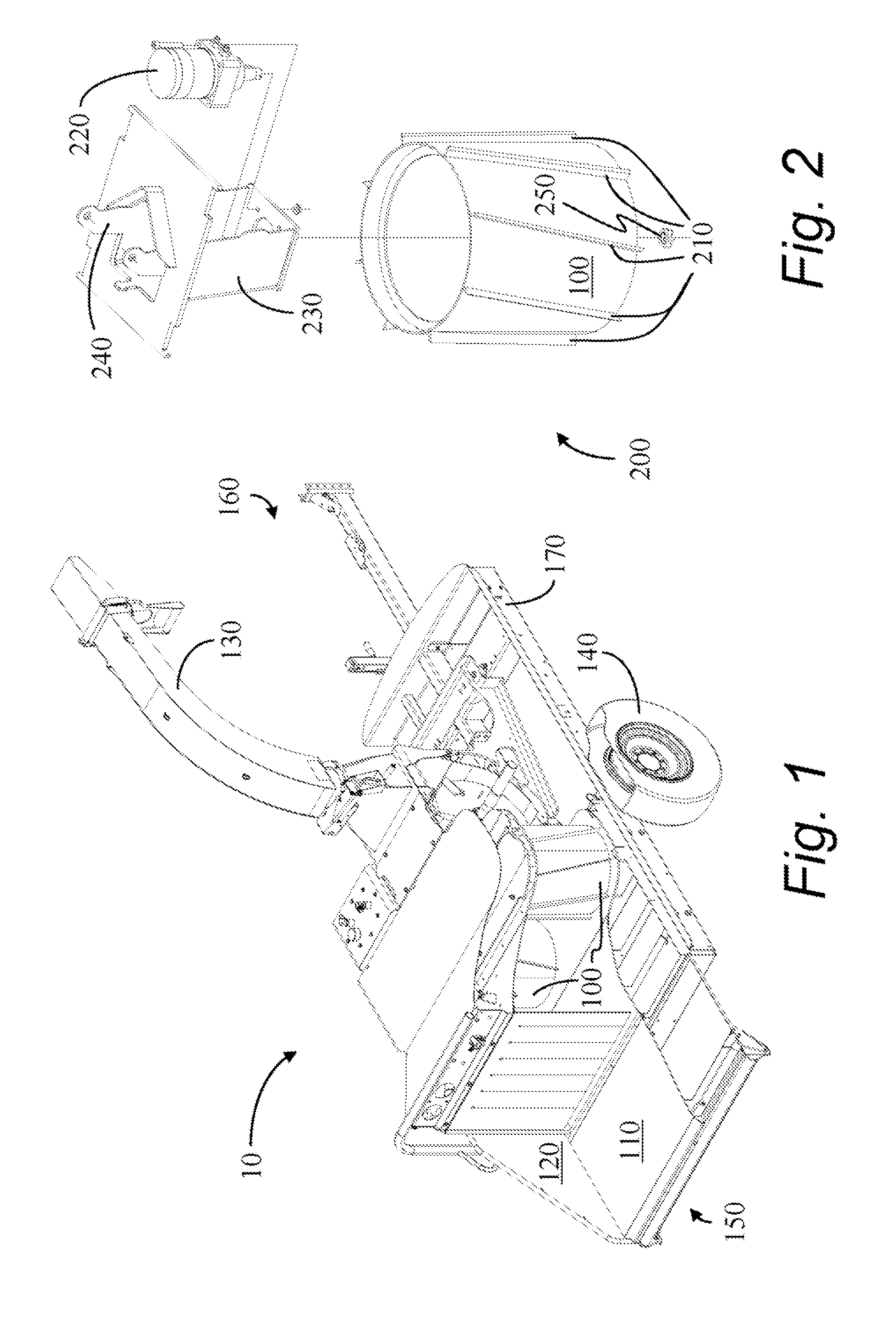
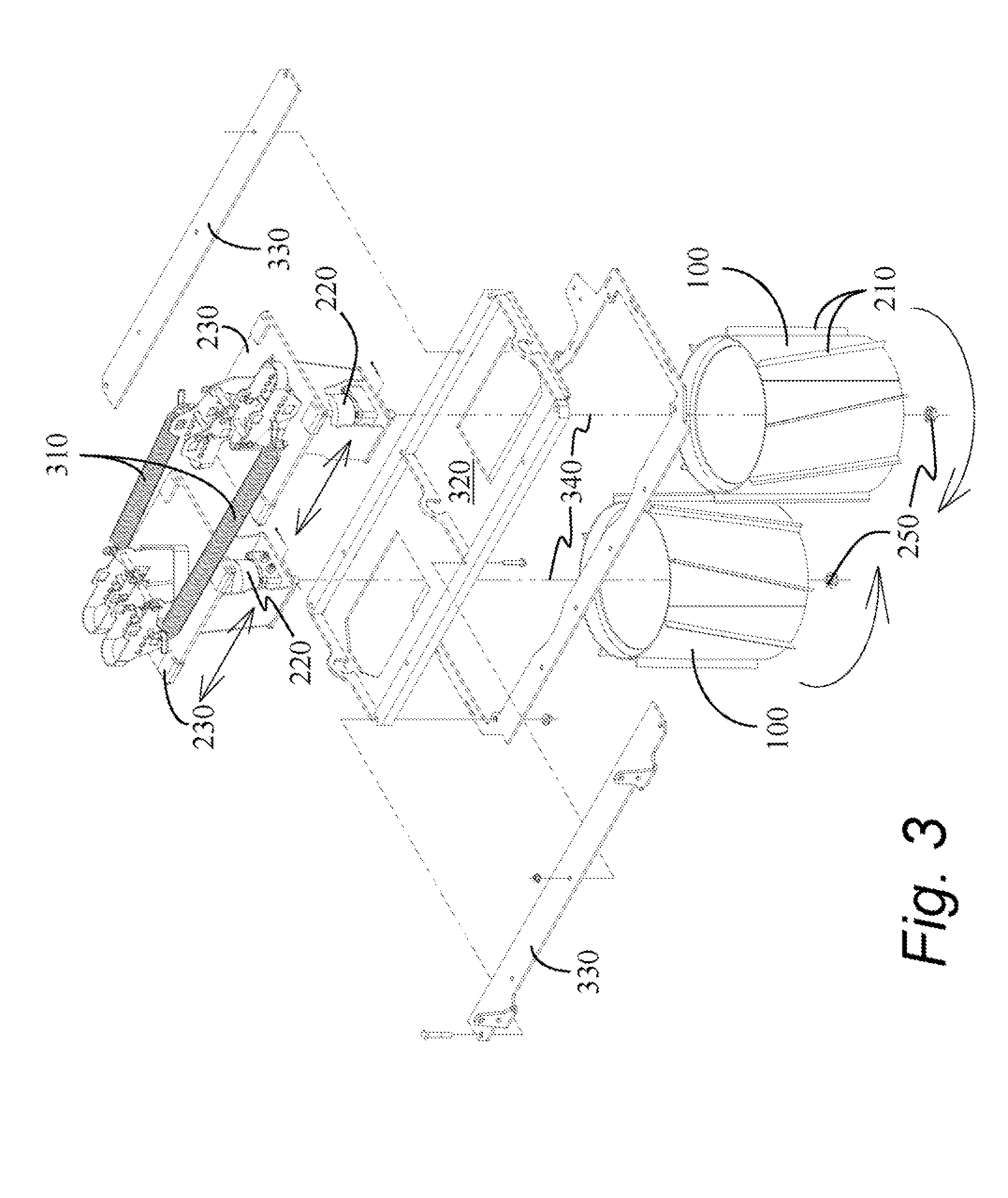
[0028]Refer now to the drawings wherein like reference numerals designate identical or corresponding parts throughout the several views. A brush chipper 10, illustrated with two feed rollers 100 of the present invention, is shown in FIGS. 1, 7, and 8. Besides the two feed rollers 100, the brush chipper comprises a feed table 110 having perpendicular sides 120 (only one shown) for structural support and for guiding logs 710 (see FIG. 7) or brush into the brush chipper 10.

[0029]Once the woody material 710 has been chipped into wood chips, the resulting wood chips are expelled through a rotatable chute 130.

[0030]The brush chipper 10 is often mounted on a frame 170 to which wheels 140 (only one shown) are operatively attached, as shown, however, tracks and skids may also be used, and the brush chipper 10 may be stationary as well. The present invention is not limited to any particular conveyance apparatus, nor does it require the brush chipper 10 be portable. The wheels 140 or other str...


PUM

PropertyMeasurementUnit
angleaaaaaaaaaa
axes of rotationaaaaaaaaaa
rotationaaaaaaaaaa

Abstract

An improved feed roller assembly wherein the feed roller provides a force perpendicular to the feed direction of the brush material. In a first embodiment, cleats that are not parallel to an axis of rotation of the feed roller are affixed to a periphery of the feed roller. When the feed roller is oriented with its axis of rotation in a substantially vertical position, each cleat is arranged with its upper end ahead of its lower end, in a direction of rotation. This configuration provides a downward force on the logs or brush being fed into the chipper, thereby reducing the occurrence of bucking. In an additional embodiment, the axes of rotation of the feed rollers lean toward the outfeed end of the brush chipper.

Description

CROSS REFERENCE TO RELATED APPLICATIONS[0001]Not applicable.STATEMENT REGARDING FEDERALLY SPONSORED RESEARCH OR DEVELOPMENT[0002]Not applicable.REFERENCE TO MICROFICHE APPENDIX[0003]Not applicable.BACKGROUND OF THE INVENTION[0004]1. Field of the Invention[0005]The present invention relates generally to a brush chipper. More particularly the present invention relates to an improved feed roller system for feeding brush into the brush chipper.[0006]2. Background Art[0007]Chippers for trees, brush and other woody material, herein referred to collectively as “brush chippers,” having a pair of feed rollers for feeding the wood or brush into the chipper mechanism are well known. One such device is described in U.S. Pat. No. 5,088,532, which is hereby incorporated in its entirety by reference. As clearly shown in FIG. 3 of U.S. Pat. No. 5,088,532, a plurality of straight cleats is included around the periphery on the feed rollers for engaging the brush being fed into the chipper.[0008]In U....

Claims


Application Information

Patent Timeline
16 Jun 2009
Publication
US7546964B2
IPC
B02C19/00
CPC
B02C18/145; B02C18/2283; B27L11/002; A01G3/002; B27B25/02
Inventors
BOUWERS, JOHN T. B.