Flexible clamping apparatus for medical devices

a technology for medical devices and clamping devices, which is applied in the direction of light support devices, washstands, scaffold accessories, etc., can solve the problems of design ill-equipped to move equipment in and out of the way at bedside as needed

Active Publication Date: 2009-06-16
KPR U S LLC
View PDF139 Cites 73 Cited by
  • Summary
  • Abstract
  • Description
  • Claims
  • Application Information

AI Technical Summary

Benefits of technology

[0005]In another aspect, a clamp for use in connecting a medical device to a support generally comprises first and second generally opposed clamp elements and a connector interconnecting the first and second clamp elements. The first and second clamp elements define a first receptacle for receiving an end of the support therein and a second receptacle for receiving a mounting structure of the medical device therein. At least one of the first and second clamp elements defines a device catch in the second receptacle. The connector is selectively movable between a first position in which the clamp elements are adapted to frictionally engage the end of the support and the mounting structure of the device to resist relative rotation between the support, clamp and medical device; and a second position in which the clamp elements are relatively farther apart than in the first position and the device catch is positioned to prevent withdrawal of the mounting structure of the medical device from the second receptacle thereby permitting the device to be rotated with respect to the support without releasing connection to the support.
[0006]In yet another aspect, a method of supporting a medical device on a flexible shaft to permit selective rotation of the medical device relative to the flexible shaft without loss of interconnection with the shaft generally comprises rotating a connector to move first and second clamp elements to an open position. Inserting a mounting structure of the medical device into a second receptacle defined by the first and second clamp elements. Then rotating the connector to move the first and second clamp elements to a fully closed position thereby clamping the mounting structure in a receptacle defined by the first and second clamp elements for resisting relative rotation of the mounting structure relative to the flexible shaft. Lastly, loosening the clamp to a position in which the mounting structure and medical device are free to rotate, while the medical device is retained from moving out of the receptacle.

Problems solved by technology

These existing designs are ill-equipped for moving equipment in and out of the way at bedside as needed when providing medical care.

Method used


Image

  • Flexible clamping apparatus for medical devices
  • Flexible clamping apparatus for medical devices
  • Flexible clamping apparatus for medical devices

Examples


Embodiment Construction

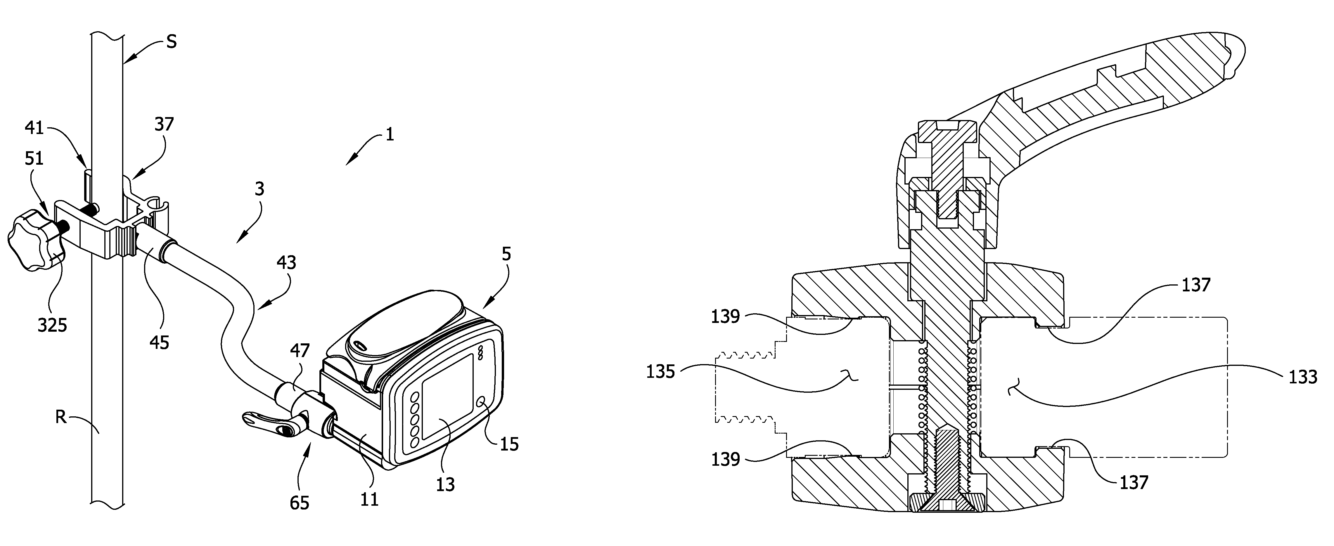
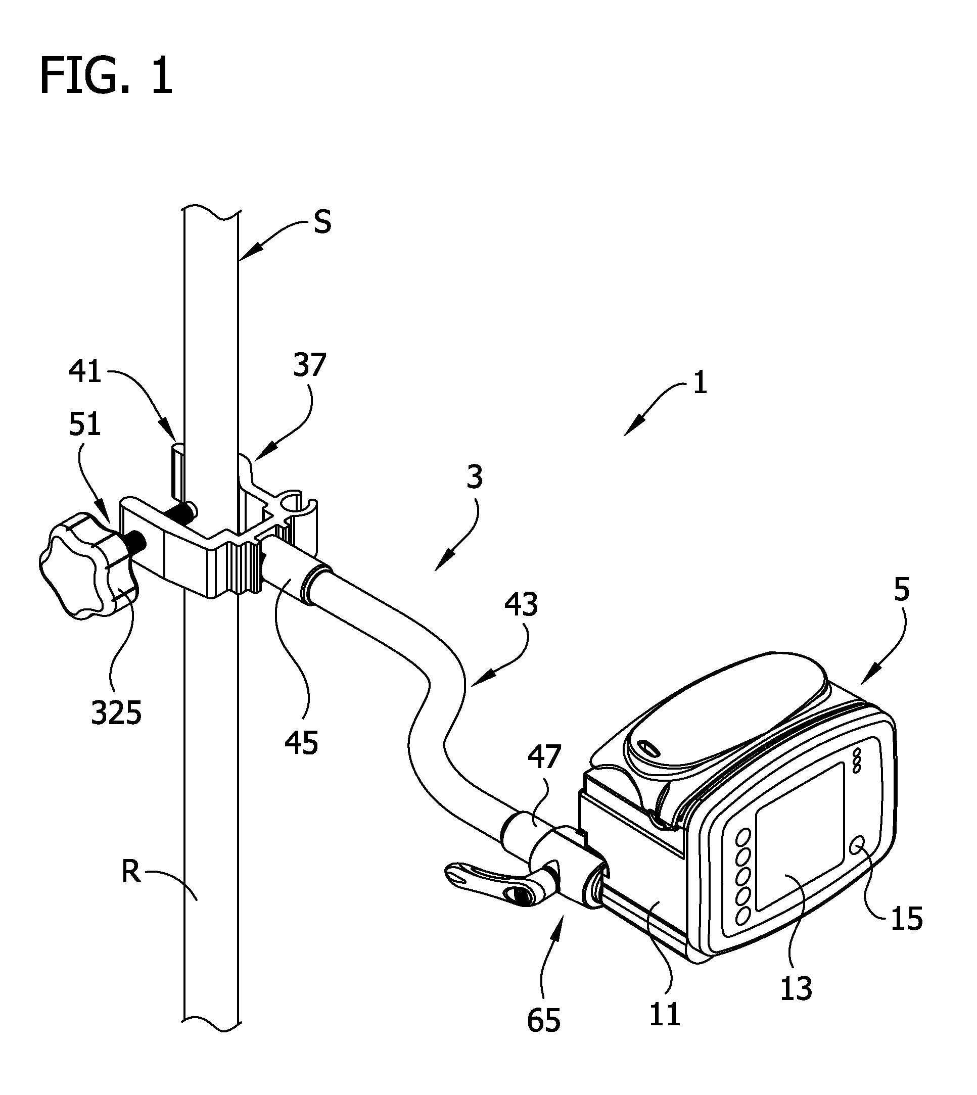
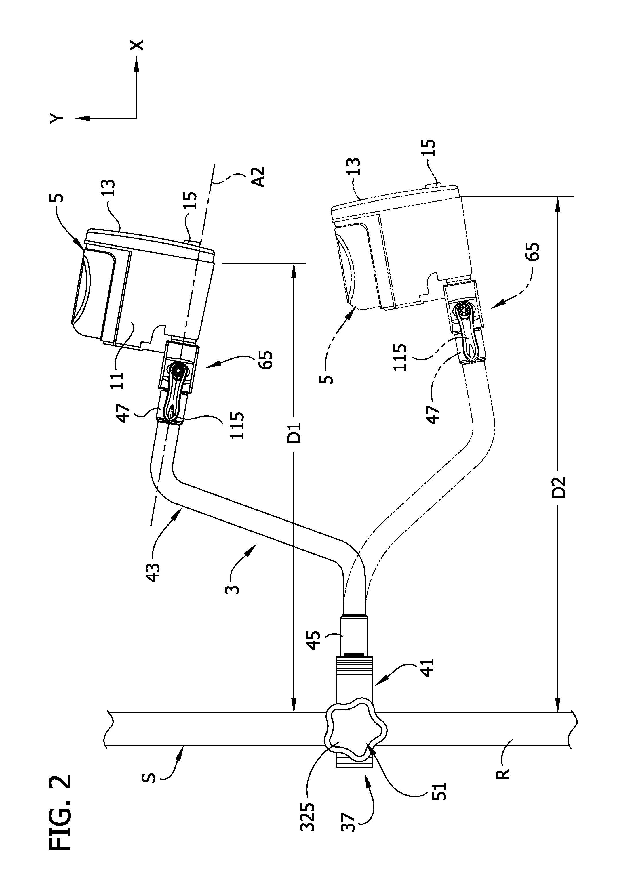
[0029]Referring now to the drawings and in particular to FIGS. 1-3, a powered medical device assembly 1 includes a clamping apparatus 3 releasably attached to a support member S to support a medical device 5 on the support member (the reference numerals designating their subjects generally). In the embodiment of FIG. 1, the support member S is a vertical IV pole having a cylindrical rod R extending up from a stand (not shown) that is commonly used to support medical paraphernalia such as IV bags (not shown) in a hospital or other healthcare environment. As discussed further below, the clamping apparatus 3 is capable of mounting the medical device 5 on support members having other than cylindrical shapes. The clamping apparatus 3 is configured to allow full range of motion (i.e., six-degrees of freedom of motion) of the medical device 5 relative to the support member S so the medical device can be positioned for better viewing and adjustment. The clamping apparatus 3 may be more broa...


PUM


Abstract

A clamping apparatus of the present invention is used in a medical environment to rotationally and releasably secure a device to a support member. The clamping apparatus includes a device clamp having first and second clamp elements and a connector interconnecting the clamp elements. The clamp elements define a first receptacle for receiving a support and a second receptacle for receiving a mounting structure. At least one clamping element defines a device catch in the second receptacle. The connector is selectively moveable between a first position in which relative rotation between the flexible shaft, device clamp and device is resisted, and a second position in which the device is permitted to rotate without releasing connection to the support. A method of supporting a medical device on a support to permit selective rotation of the medical device relative to a flexible shaft without loss of interconnection is also disclosed.

Description

FIELD OF THE INVENTION[0001]This invention relates generally to the field of support apparatus for medical devices and more particularly to a medical device mounting apparatus having a clamping apparatus.BACKGROUND OF THE INVENTION[0002]Medical devices such as enteral feeding pumps are typically attached to an IV pole or other support member by a pole clamp or other attachment device that holds the pump in a fixed position relative to the support member. One existing pole clamp design permits one degree of freedom of motion of the pump relative to the pole by allowing the pump to be rotated or indexed between fixed orientations relative to the IV pole. The indexing requires a substantial portion of the fixture be located on the clamp. Another existing pole clamp design permits two or more degrees of freedom of motion such that the pump may be moved horizontally, vertically, or laterally relative to the IV pole for easier viewing and operation. An example is embodied in co-assigned a...

Claims


Application Information

Patent Timeline
Patent Type & Authority Patents(United States)
IPC IPC(8): A47B96/06
CPCA61M5/1415F16M11/105F16M11/2021F16M11/24F16M13/02A61M2209/08F16M2200/022F16M2200/044F16M13/022
Inventor WALKER, CLARENCE
Owner KPR U S LLC
Why Eureka
Try Eureka