Liquid discharge recording head and ink jet recording apparatus

a recording head and liquid discharge technology, applied in electrical devices, printed circuits, printing, etc., can solve the problems of increasing material cost, increasing the size of discharged liquid, and disadvantages of the prior art, and achieve the effect of improving the sealing structure of the electrically connecting portion

Inactive Publication Date: 2009-06-16
CANON KK
View PDF15 Cites 31 Cited by
  • Summary
  • Abstract
  • Description
  • Claims
  • Application Information

AI Technical Summary

Benefits of technology

[0016]The present invention aims to provide a liquid discharge recording head with improved sealing structure of the electrically connecting portion between the recording element and the flexible wiring substrate.
[0017]The present invention also aims to provide a liquid discharging recording head that suppresses the expansion of the sealing agent on the flexible wiring substrate and enhances the image recording quality while preventing the sealing agent from blocking the discharge port and maintaining the reliability of the ink discharge performance.
[0019]The present invention also aims to provide a liquid discharge recording head that stops the sealing material at the peripheral rim of the bonding hole and prevents it from flowing to the device hole side and effectively prevents the flow of the sealing material to the discharge port when the bonding hole facing the electrically connecting portion is provided independently from the device hole.

Problems solved by technology

However, the above prior arts have disadvantages.
Thus, the sealing agent having properties different from the first sealing agent 1201 must be used for the second sealing agent 1202, and the usage of two types of sealing agents increases the material cost.
Recently, the size of the discharged liquid tends to be increasingly microscopic due to the demand of higher fineness of the image recording quality.
However, the higher the height of the sealing agent 1202 on the flexible wiring substrate 1300, the spacing between the nozzle plate 1102 and the recording medium must be made larger, which causes lowering of image recording quality.
In other words, in the conventional configuration described above, the expanded second sealing agent is likely to contact the recording medium, which is one cause of inhibiting reduction of the distance to papers.
Hei 8-048042, for example, but faces a challenge in that height H1 is also required in terms of sealing the base film of the flexible wiring substrate.

Method used


Image

  • Liquid discharge recording head and ink jet recording apparatus
  • Liquid discharge recording head and ink jet recording apparatus
  • Liquid discharge recording head and ink jet recording apparatus

Examples


first embodiment

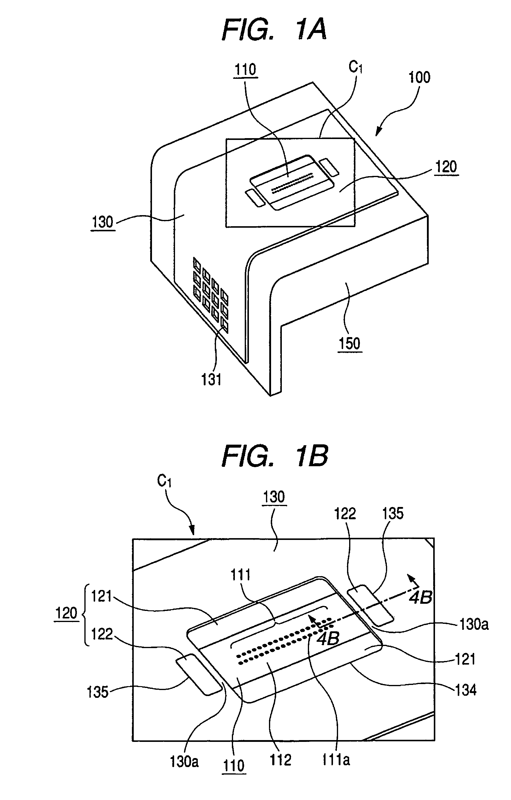
[0052]In FIGS. 1A to FIGS. 4B, the liquid discharge recording head of the first embodiment is shown. The recording head 100 serving as the liquid discharge recording head is a side shooter type recording head that performs recording using the recording element 110 having an electrothermal conversion body for generating film boiling according to the electric signal with respect to the ink serving as liquid.

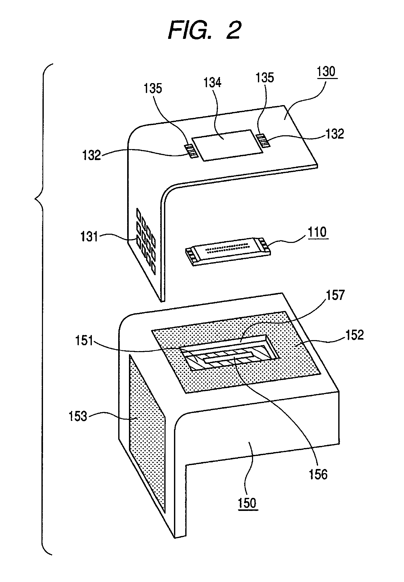
[0053]As shown in FIGS. 1A and 1B, the recording head 100 is configured by a recording element 110 with a nozzle plate 112, a flexible wiring substrate 130, a support member 150 serving as a support means for fixing and supporting the above and the like. The flexible wiring substrate 130 includes an external signal input terminal 131 connected to an external wiring (not shown), a device hole 134 for exposing the nozzle plate 112 of the recording element 110, and a pair of bonding holes 135 serving as an auxiliary opening. The side surface of the recording element 110 in the device ...

second embodiment

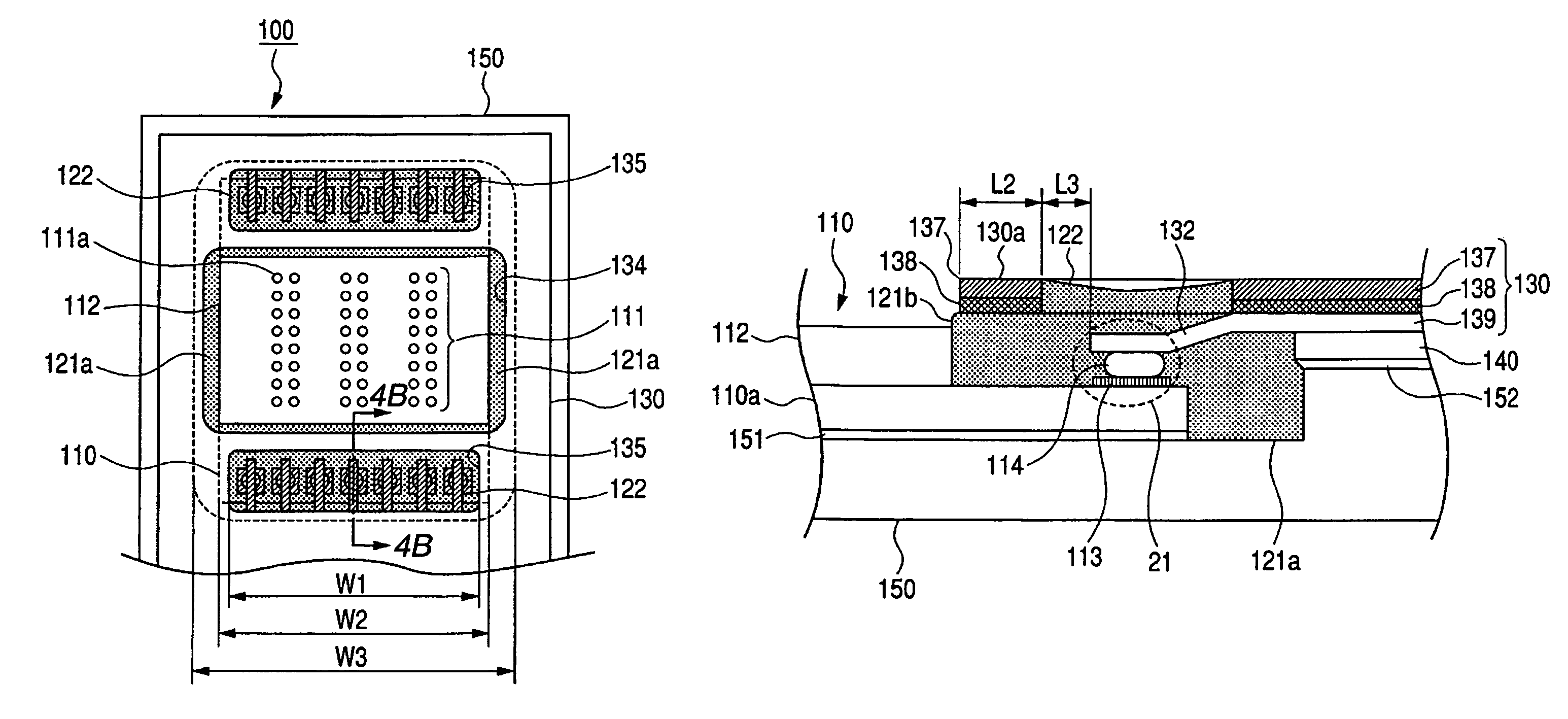
[0073]FIG. 5 to FIGS. 7A and 7B show the recording head according to a second embodiment. The following explanation is focused on the difference from the first embodiment. The part not particularly mentioned is the same as the first embodiment. In the present embodiment, as shown in FIG. 6, a rib-shaped protrusion 112a is arranged at a position facing the separating band 130a of the flexible wiring substrate 130 and adjacent to the end of the nozzle plate 112 on the heater board 110a. Thus, a groove 112b extending parallel to the separating band 130a is formed. The groove 112b secures the filling path when one portion 121b of the first sealing agent 121 is filled to between the separating band 130a of the flexible wiring substrate 130 and the recording element 110 by the capillary phenomenon.

[0074]As shown in FIG. 5 and FIGS. 7A and 7B, if it is the recording head capable of discharging inks of three colors, for example, the ink supply path and the discharge port column correspondin...

third embodiment

[0076]FIG. 8 and FIGS. 9A and 9B show a third embodiment. The following explanation is made focusing on the difference from the first embodiment. The part not particularly mentioned is the same as the first embodiment. The recording head of the present embodiment is configured so that the width of the central part of the device hole 134 of the flexible wiring substrate 130 is narrow. Specifically, the length L5 of the central part of the device hole 134 shown in FIG. 8, for example, is formed to be smaller with respect to the length L4 of the outer peripheral side. That is, as shown in FIG. 9B, the side facing the bonding hole 135 of the device hole 134 is bent in a direction separating away from the recording element 110 near the end. The intersecting angle of the separating band 130a and the side surface 110b of the recording element 110 is θa>θb where θa is the separating band side and θb is the first opening side.

[0077]The present embodiment has a configuration in which the seal...


PUM


Abstract

A liquid discharge recording head includes a recording element with a discharge port for discharging liquid and an electrically connecting portion arranged adjacent to the discharge port and receiving an electric signal for controlling the discharge of the discharge port. The liquid discharge recording head further includes a flexible wiring substrate for covering at least a portion of the recording element. The flexible wiring substrate includes each of a device hole for exposing the discharge port and a bonding hole arranged facing the electrically connecting portion independently. The liquid discharge recording head further includes a sealing agent for covering at least a portion of the electrically connecting portion and filled to at least a portion of the bonding hole. Thus, a liquid discharge recording head that enhances recording performance and that has superior productivity while maintaining reliability of the recording performance is provided.

Description

[0001]This application is a continuation of International Application No. PCT / JP2005 / 022990, filed Dec. 8, 2005, which claims the benefit of Japanese Patent Application No. 2004-354793, filed Dec. 8, 2004, Japanese Patent Application No. 2004-359934, filed Dec. 13, 2004, Japanese Patent Application No. 2005-214675, filed Jul. 25, 2005, and Japanese Patent Application No. 2005-320984, filed Nov. 4, 2005.BACKGROUND OF THE INVENTION[0002]1. Field of the Invention[0003]The present invention relates to a liquid discharge recording head and an ink jet recording apparatus, in particular, to a sealing structure of an inner lead mounting part in the liquid discharge recording head.[0004]2. Related Background Art[0005]The recording apparatus of liquid discharge method such as an ink jet printer is a so-called recording apparatus of non-impact recording method that is capable of fast recording, and recording on various recording media, and that has a feature of barely producing noise during re...

Claims


Application Information

Patent Timeline
Patent Type & Authority Patents(United States)
IPC IPC(8): B41J2/14B41J2/16
CPCB41J2/14024B41J2/14072H05K3/361H05K3/328H05K2201/0367H05K2201/0397H05K2201/10977
Inventor KAWAMURA, SHOGOMORI, TOSHIHIROFUKAI, HISASHINAKAJO, NAOKI
Owner CANON KK
Why Eureka
Try Eureka