Potential separation for filling level radar

a radar and level technology, applied in the field of filling level measurement, can solve the problems of affecting the implementation, igniting or damage of feed materials, and affecting the signal of microwave transmission signals and receiving signals, and achieve the effect of simple signal separation

Active Publication Date: 2009-06-16
VEGA GRIESHABER GMBH & CO
View PDF13 Cites 11 Cited by
  • Summary
  • Abstract
  • Description
  • Claims
  • Application Information

AI Technical Summary

Benefits of technology

[0014]In this way the measured values may be transmitted by way of the two-conductor current loop. In this process, the actual value of the regulation is conveyed from the two-conductor loop to the input- and output circuit and may not need to be transmitted by way of the potential separation.
[0030]Digital signals may be easy to separate. The expenditure involved in potential separation of digital signals may be significantly less than the corresponding expenditure that would have to be incurred for separating analogue signals.
[0032]The separation of direct-voltage-free alternating signals may also be simple when compared to the separation of analogue direct-voltage signals.
[0035]According to a further exemplary embodiment of the present invention, transmission of the filling level measuring value takes place directly from the second microcontroller (which is located in the second region) by way of potential separation (for example by means of an optical coupler) directly to a current regulator of the input- and output circuit. In this way the first microprocessor (which is located in the first region of the electronics unit) is bypassed. In this way, even in the case of a malfunction in the first microprocessor, reliable transmission of signals from the second microprocessor to the current regulator of the input- and output circuit may be ensured.
[0047]In this way a method may be provided which may ensure simple separation of signals within the electronics unit. The signals to be separated are, for example, digital signals or direct-voltage-free alternating signals.

Problems solved by technology

Thus, undesirable spark-over could, for example, lead to ignition of, or damage to, the feed material.
However, this may result in signal impairment of the microwave transmission signal and receiving signal in the form of signal attenuation or reflections due to mismatching.
In particular in the case of very high microwave frequencies implementation may be made difficult because discrete components for separation may not be available, and line elements, as a result of their small dimensions, may only be produced with reproducibly good characteristics at great expense.
This may not be possible with simple optical couplers.

Method used


Image

  • Potential separation for filling level radar
  • Potential separation for filling level radar
  • Potential separation for filling level radar

Examples


Embodiment Construction

[0068]In the following description of the figures the same reference characters are used for identical or similar elements.

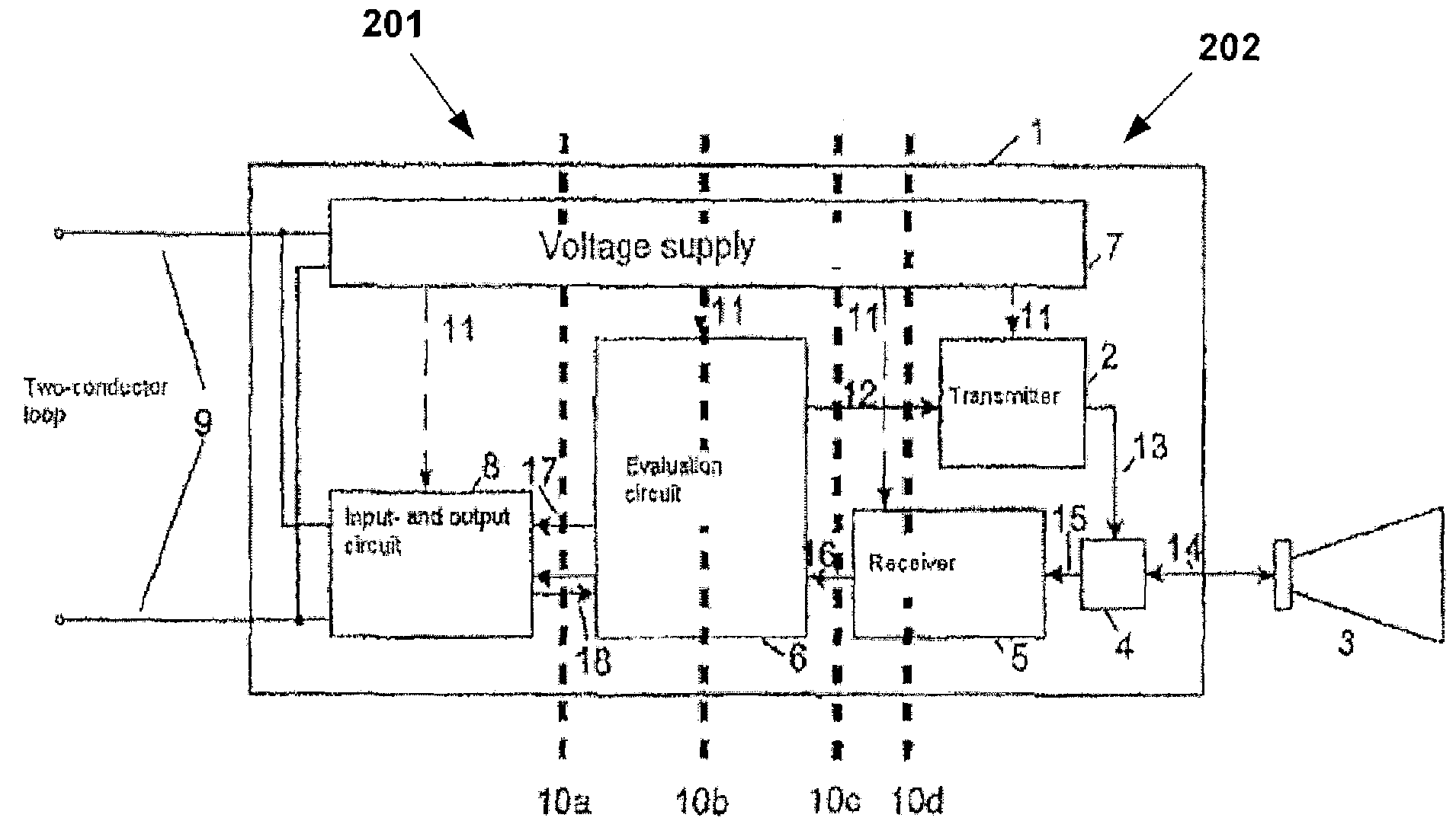
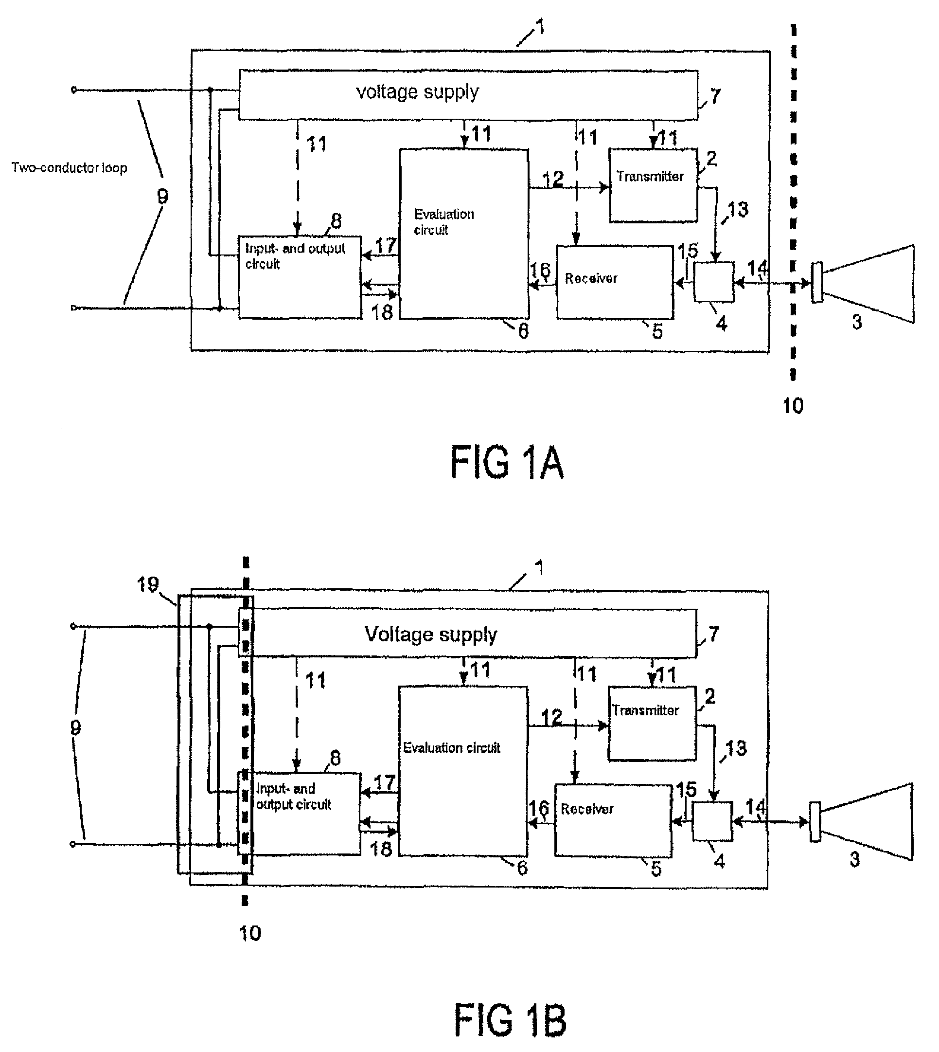
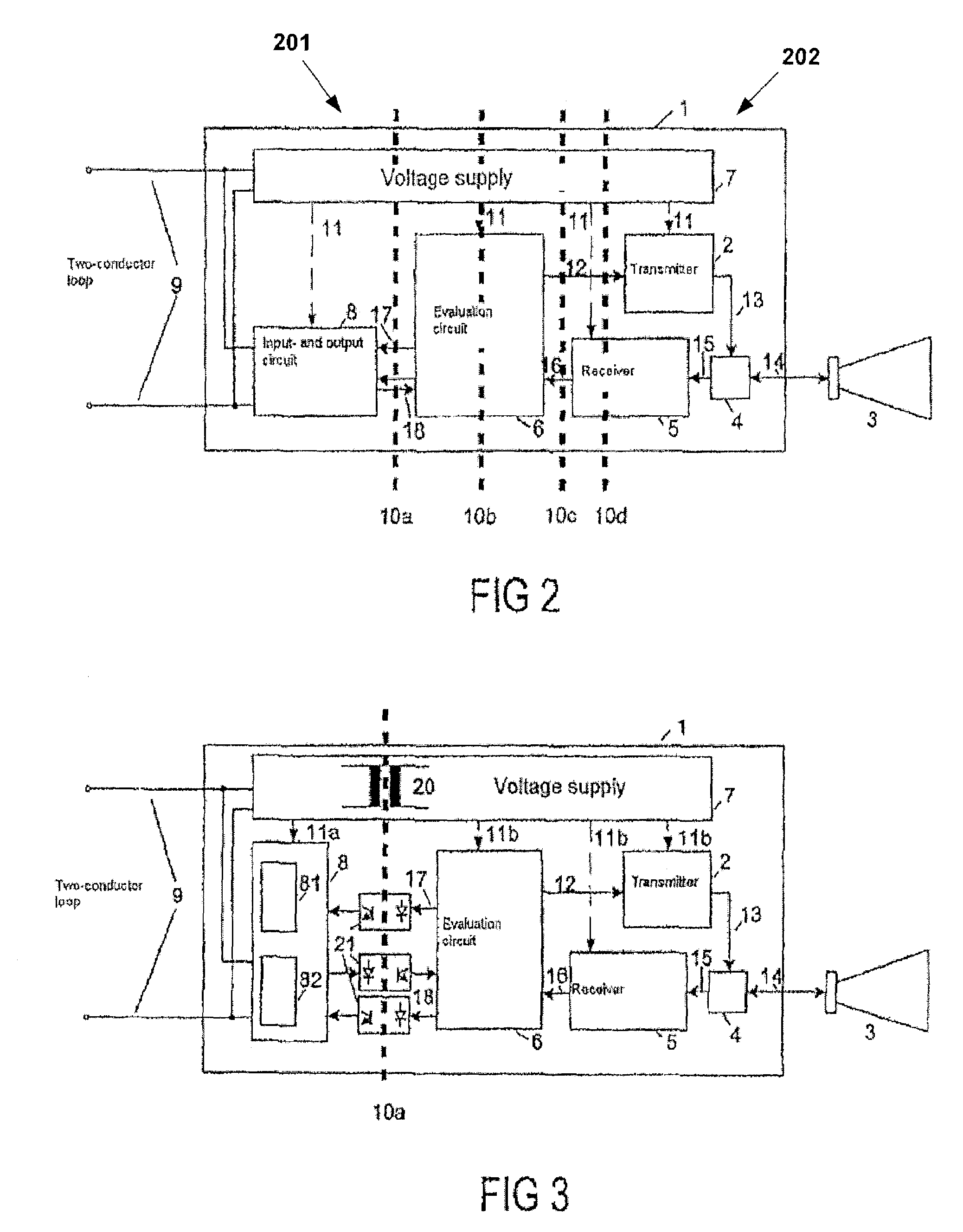
[0069]FIG. 1A shows a diagrammatic view of a filling level radar device with potential separation 10 in the microwave path 14. In this arrangement the filling level radar comprises an electronics unit 1 that is connected to a two-conductor loop 9. The electronics unit 1 comprises a voltage supply 7 with a DC / DC converter, one or several filters, one or several voltage regulators and one or several storage capacitors. Furthermore, the electronics unit 1 comprises an input- and output circuit 8, an evaluation circuit 6, a transmitter 2, a receiver 5 and a circuit for separating the transmission and receiving path 4, which comprises, for example, a directional coupler or a circulator.

[0070]The voltage supply 7 is connected to the input- and output circuit 8, the evaluation circuit 6, the transmitter2 and the receiver 5 by way of the line 11 and supplies these units...


PUM


Abstract

Both in potential separation in the microwave path, and in potential separation directly between the two-wire loop and the output circuit, the quality of signal transmission may be negatively affected. A filling level radar device with potential separation within the electronics unit is stated, wherein potential separation does not separate analogue signals but instead separates digital signals or direct-current-free alternating signals. For example, the separation line leads through digital signal connections or alternating-voltage signal connections. As a result of this the expenditure for potential separation may be reduced and the transmission quality may be improved.

Description

REFERENCE TO RELATED APPLICATIONS[0001]This application claims the benefit of the filing date of German Patent Application Ser. No. 10 2006 015 659.5 filed Apr. 4, 2006; U.S. Provisional Patent Application Ser. No. 60 / 789,227 filed Apr. 4, 2006; and U.S. Provisional Patent Application Ser. No. 60 / 763,020 filed Jan. 27, 2006, the disclosure of which applications is hereby incorporated herein by reference.FIELD OF THE INVENTION[0002]The present invention relates to filling level measuring. In particular the present invention relates to filling level radar with potential separation for measuring the filling level in a container and for connection to a two-wire loop, as well as to a method for measuring the filling level.BACKGROUND INFORMATION[0003]Known filling level measuring devices comprise an aerial for transmitting and receiving radar waves or microwaves, and an electronics unit which generates the signals to be emitted and which evaluates the received signals.[0004]Furthermore, p...

Claims


Application Information

Patent Timeline
Patent Type & Authority Patents(United States)
IPC IPC(8): G01R27/32
CPCG01F23/284G01S7/003G01S7/02G01S7/03G01S13/10G01S13/88
Inventor GRIESSBAUM, KARLMOTZER, JUERGENDECK, THOMASFEHRENBACH, JOSEFRAUER, WINFRIED
Owner VEGA GRIESHABER GMBH & CO
Why Eureka
Try Eureka