Transmitter, receiver, data transfer system, transmission method, reception method, computer program for transmission, computer program for reception, and recording medium

a data transfer system and receiver technology, applied in the field of transmission methods, computers for receiving and receiving, computer programs for receiving, and receiving methods, can solve the problems of increasing the transfer time, unable to transmit data, and poor transfer efficiency of irda schemes, so as to achieve reliable and quick data transfer

Inactive Publication Date: 2009-06-16
SHARP KK
View PDF26 Cites 7 Cited by
  • Summary
  • Abstract
  • Description
  • Claims
  • Application Information

AI Technical Summary

Benefits of technology

[0027]The present invention, conceived to address these problems, has an objective to provide a transmitter, a receiver, a data transfer system, a transmission method, a reception method, a computer program for data transmission, a computer program for data reception, a recording medium, etc., which deliver reliable and quick data transfer.
[0031]In addition, the transfer data is divided into multiple divisional data sets, and the multiple divisional data sets are transmitted. Therefore, even if the size of the transfer data is large, the transfer data can be transmitted by dividing the transfer data into an increased number of divisional data sets. The configuration and method hence improves reliability over the aforementioned remote controller in the transfer of large amounts of data.
[0032]In addition, the multiple divisional data sets are transmitted all together. Therefore, there is no need to perform a check with the receiver on a receipt of each divisional data set (or each predetermined divisional data set). Transfer efficiency is improved.
[0035]According to the configuration and method, the multiple divisional data sets and the error detection information are received all together. When the error detection section has detected no error in any of the divisional data sets, the section performs a predetermined process according to the divisional data sets. In other words, there is no need to transmit a notification to verify reception for each or two or more of the divisional data sets. It takes less time to receive all the divisional data sets.
[0036]In addition, the divisional data sets into which the transfer data is divided are received. Therefore, a large size of transfer data can be handled by increasing the number of divisional data sets. The configuration and method hence improves reliability over the aforementioned remote controller in the transfer of large amounts of data.
[0038]According to the configuration, the data transfer has high reliability, It takes less time to transfer the data.

Problems solved by technology

If the direct path between the transmitter and receiver is obstructed, no data can be transmitted.
However, the IrDA schemes show poor transfer efficiency, because as mentioned above, the transmitter device and the receiver device frequently check that data transmission / reception is being performed between the devices during a data transfer.
This adds to the transfer time, which presents problems in achieving efficient infrared data transfer.
On top of it, the time it takes to establish a data transfer connection reduces overall transfer efficiency.
If the data transfer is interrupted in the middle even for an instant, the receiver cannot receive the data, resulting in a low transfer reliability.
The remote controller scheme is not suitable for the transfer of images and other large amount data.
In addition, as mentioned above, the scheme involves reverse data, which leads to low data transfer efficiency and extended transfer time.

Method used


Image

  • Transmitter, receiver, data transfer system, transmission method, reception method, computer program for transmission, computer program for reception, and recording medium
  • Transmitter, receiver, data transfer system, transmission method, reception method, computer program for transmission, computer program for reception, and recording medium
  • Transmitter, receiver, data transfer system, transmission method, reception method, computer program for transmission, computer program for reception, and recording medium

Examples


embodiment 1

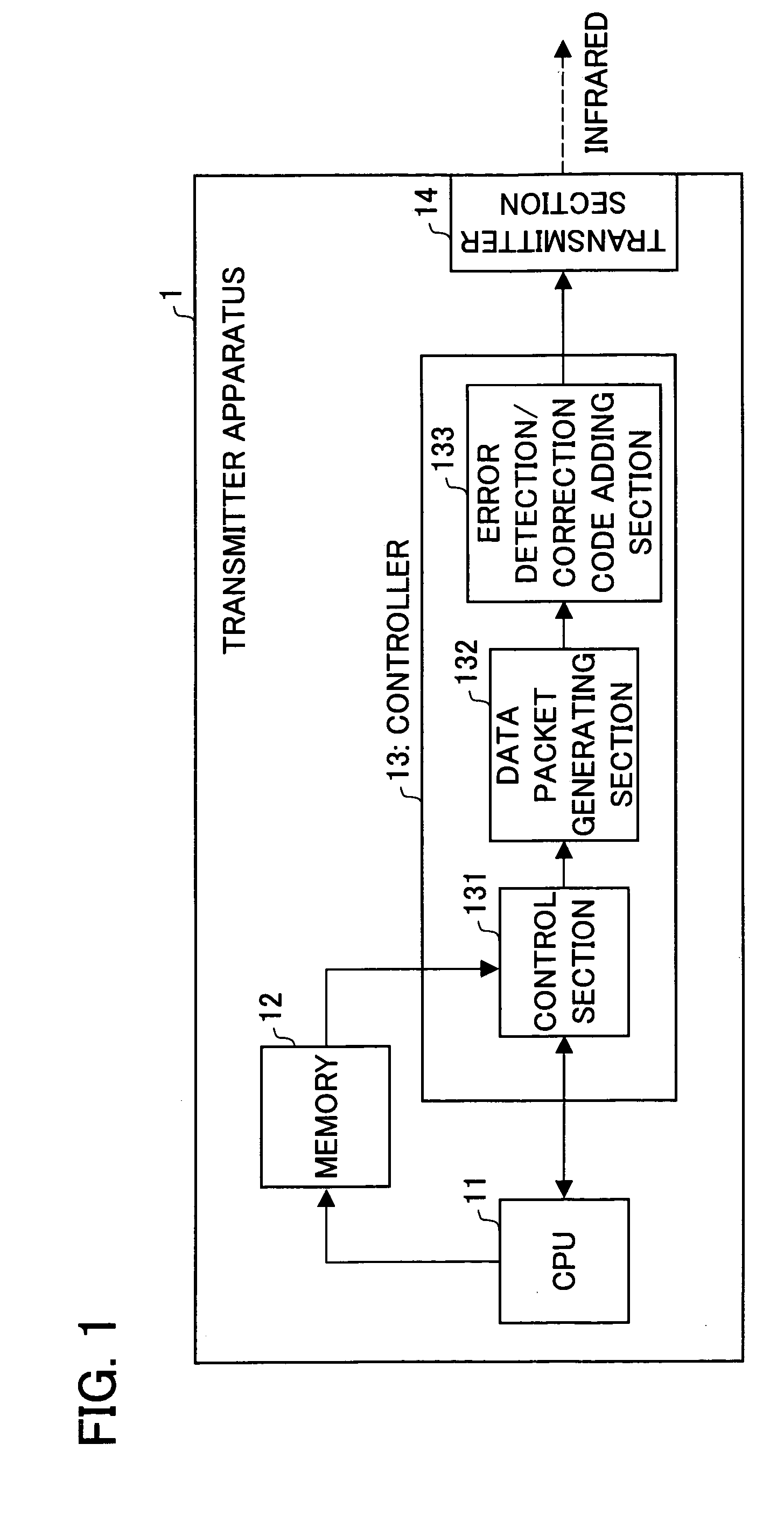
[0113]The following will describe a data transfer system in accordance with an embodiment of the present invention in reference to FIG. 1 to FIG. 3. FIG. 1 is a block diagram illustrating a configuration of a transmitter apparatus (transmitter) 1 of the present embodiment. As shown in FIG. 1, the transmitter apparatus 1 contains a CPU 11, a memory 12, a controller 13, and a transmitter section (first transmitter section) 14.

[0114]The CPU 11 performs predetermined computing in accordance with user instructions entered through an manipulation section (not shown). The predetermined computing includes a data transfer process. In response to a data transfer instruction from the manipulation section, the CPU 11 loads desired transfer data into the memory 12. Also the CPU 11 sends a transfer request to the controller 13. The CPU 11 completes a transfer process when it receives from the controller 13 a transmission complete notification indicating the end of a data transmission.

[0115]The me...

embodiment 2

[0149]In embodiment 1, the data packets are transmitted without the transmitter apparatus 1 determining the presence / absence of the receiver apparatus 2. This allows significant reductions in time it takes to transfer data. However, if no receiver apparatus 2 is present, a data packet transmission adds to the power consumption in the transmitter apparatus 1. In contrast, communicating the XID and SNRM commands and their response adds to the time it takes to transfer data as is the case with the aforementioned IrDA. The present embodiment solves these problems. Power consumption is lowered. Also, data is transferred in less time than the aforementioned IrDA.

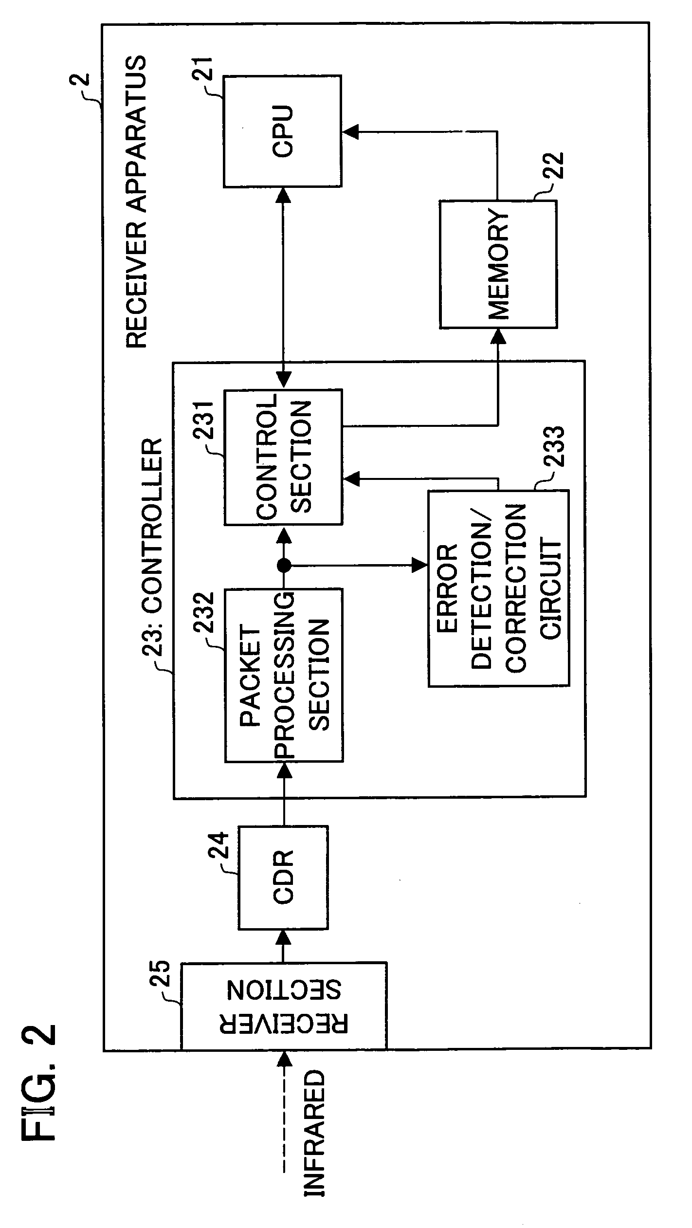
[0150]Referring to FIG. 4 to 7, a data transfer system of the present embodiment will be described. For convenience, members of the present embodiment that have the same function as members of the above embodiment, and that are mentioned in that embodiment are indicated by the same reference numerals and description thereof is omi...
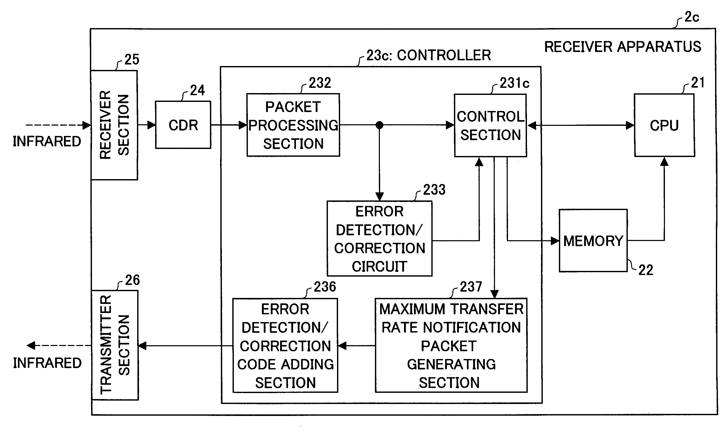
embodiment 3

[0179]Similarly to embodiment 2, the present embodiment lowers power consumption and requires less time to transfer data than the aforementioned IrDA.

[0180]Referring to FIGS. 8 to 10, a transmission system of the present embodiment will be described. For convenience, members of the present embodiment that have the same function as members of the above embodiments, and that are mentioned in those embodiments are indicated by the same reference numerals and description thereof is omitted.

[0181]FIG. 8 is a block diagram illustrating the configuration of a transmitter apparatus (transmitter) 1b of the present embodiment. As shown in FIG. 8, the transmitter apparatus 1b differs from the transmitter apparatus 1 where the CPU 11 is replaced by a CPU 11b, and the controller 13 by a controller 13b. Another difference is that the apparatus 1b contains a receiver section (first receiver section) 15 and a CDR 16.

[0182]When receiving a transfer instruction from the manipulation section, the CPU ...


PUM


Abstract

A transmitter apparatus transmits transfer data having a predetermined amount to a receiver apparatus. The apparatus includes a data packet generating section dividing the transfer data into multiple divisional data sets; an error detection / correction code adding section adding an error detection code (error detection information) by which an error in the divisional data sets is detected to each of the divisional data sets; and a transmitter section transmitting the multiple divisional data sets to which the error detection code is added all together. Thus, data transfer is very reliable. It takes less time to transfer data.

Description

[0001]This Nonprovisional application claims priority under 35 U.S.C. § 119(a) on Patent Applications Nos. 2004-145114 filed in Japan on May 14, 2004 and 2004-231635 filed in Japan on Aug. 6, 2004, the entire tents of which are hereby incorporated by reference.FIELD OF THE INVENTION[0002]The present invention relates to, among others, data transmitters, data receivers, data transfer systems, data transmission methods, data reception methods, computer programs for data transmission, computer programs for data reception, and storage media.BACKGROUND OF THE INVENTION[0003]We have recently seen increasingly popular use of mobile phones which come with imaging functions. They are used to take pictures and send the image data to televisions, printers, or like devices where the data is processed for display or in other predetermined manners.[0004]The mobile phone interfaces to the television, printer, or personal computer (PC) through such an infrared link as IrDA (Infrared Data Associatio...

Claims


Application Information

Patent Timeline
Patent Type & Authority Patents(United States)
IPC IPC(8): H04B1/18H04L29/06G06F3/12G06F11/00H04B10/11H04B10/114H04J1/00H04Q7/00
CPCH04L1/0041H04L1/0053H04L1/1835H04L1/1867
Inventor SAKAI, KOJINAOE, HITOSHIFUKAE, FUMIHIROOSAWA, SHOHEI
Owner SHARP KK
Why Eureka
Try Eureka