Method and apparatus for graphical display of a condition in a building system with a mobile display unit

a mobile display and condition technology, applied in the field of building systems, can solve the problems of limited ability to associate sensor values with other building system components or general building attributes, limited ability to use such data, and building components are not normally integrated into an extensive building-wide communication infrastructur

Active Publication Date: 2009-06-16
SIEMENS IND INC
View PDF10 Cites 196 Cited by
  • Summary
  • Abstract
  • Description
  • Claims
  • Application Information

AI Technical Summary

Problems solved by technology

Nonetheless, most building automation systems have limited ability to associate sensor values with other building system components or general building attributes.
While systems with such graphics provide at least some integrated visible representation of portions of the building automation system, the ability to use such data is limited.
These building components, however, are not normally integrated into an extensive building-wide communication infrastructure.
Attempts to obtain data from each specific device using a dedicated communication channel can thus be extremely cost-prohibitive and technically challenging considering the wiring needs.
Thus, in the event of a component failure or malfunction, an appropriate representative may or may not be available to attend to the component.
One issue associated with various building system components is thus the elapsed time between discovery of a malfunction, communication of the malfunction to the appropriate service provider, and the response time of the provider.
Such elapsed time may have dangerous and costly consequences.
Even in the event the malfunction is not dangerous or costly, however, a poorly maintained building is not conducive to productive and satisfied occupants.
Moreover, even an individual that is familiar with a particular system may find it difficult to accurately communicate the nature of a problem to a remotely located expert.
Another issue that arises is the loss of information on specific components over the lifetime of the component.
Too frequently, historical data is either misplaced or available in a form that is not convenient.
This problem is exacerbated when different organizations sell, install, and maintain the components since the data may not be passed from one organization to the next organization.
Even when the data is maintained within a central location, however, a technician working on at the site of a problem is frequently confronted with additional needs for information about the system.

Method used


Image

  • Method and apparatus for graphical display of a condition in a building system with a mobile display unit
  • Method and apparatus for graphical display of a condition in a building system with a mobile display unit
  • Method and apparatus for graphical display of a condition in a building system with a mobile display unit

Examples


Embodiment Construction

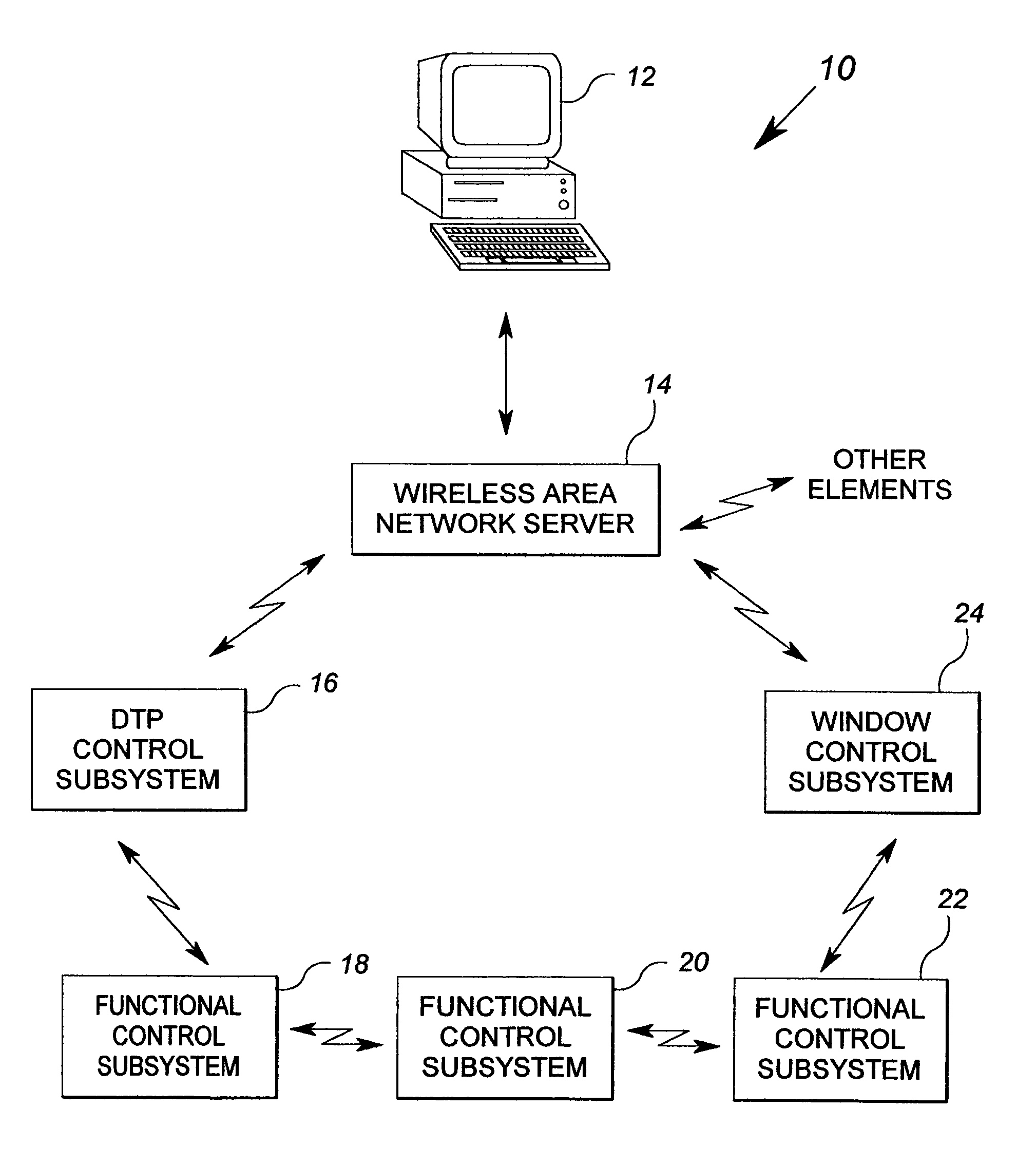
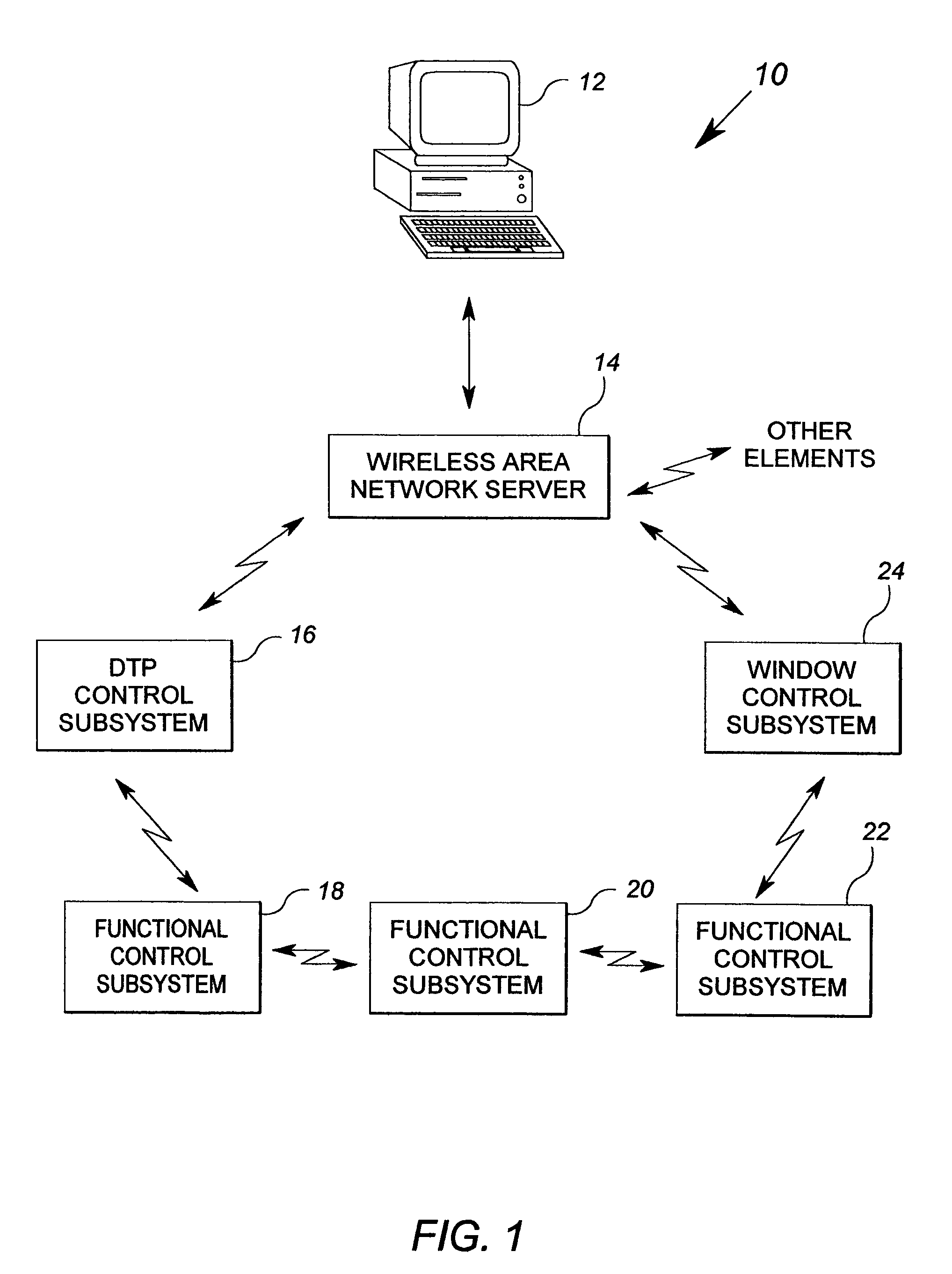
[0044]FIG. 1 shows a block diagram of an exemplary building control system in accordance with the present invention. The building control system 10 includes a supervisory computer 12, a wireless area network (WAN) server 14, a distributed thermal plant (DTP) control subsystem 16, three functional control subsystems 18, 20 and 22, and a window control subsystem 24. The building control system 10 includes only the few above-mentioned elements for clarity of exposition of the principles of the invention. Typically, many more functional control subsystems, as well as many more window, thermal plant, and other building HVAC subsystems, will be included into a building control network. Those of ordinary skill in the art may readily incorporate the methods and features of the invention described herein into control systems of larger or smaller scale.

[0045]In general, the building control system 10 employs a first wireless communication scheme to effect communications between the supervisor...


PUM

PropertyMeasurementUnit
temperatureaaaaaaaaaa

Abstract

A method and apparatus uses a stored model of a building system to render an image showing a condition sensed of the building control system on a mobile display unit. The mobile display unit may be wirelessly integrated into the building control system. The mobile display unit may operate based upon voice commands and / or eye tracking.

Description

[0001]This application is a continuation in part of U.S. application Ser. No. 11 / 090,954, filed Mar. 25, 2005, now Pat. No. 7,383,148 which claims the benefit of U.S. provisional application Ser. No. 60 / 556,119, filed Mar. 25, 2004, now expired.FIELD OF THE INVENTION[0002]The present invention relates generally to building systems, and more particularly, to methods and apparatus for displaying building system data.BACKGROUND OF THE INVENTION[0003]Building automation systems are comprehensive and distributed control and data collection systems for a variety of building automation functions within a building system. Such functions may include comfort systems (also known as heating, ventilation and air condition or HVAC systems), security systems, fire safety systems, as well as others. Building automation systems include various end points from which data is collected. Examples of such end points include temperature sensors, smoke sensors, and light sensors. Building automation system...

Claims


Application Information

Patent Timeline
Patent Type & Authority Patents(United States)
IPC IPC(8): G06F15/00F24F7/00F24F11/00G01K13/00G05D23/00G06F19/00G08B25/00
CPCF24F11/0086F24F2011/0067F24F11/30F24F11/54F24F11/52F24F11/58F24F11/64
Inventor AHMED, OSMAN
Owner SIEMENS IND INC
Why Eureka
Try Eureka