Boxing machine

a boxing machine and box body technology, applied in the field of boxing machines, can solve the problems of large working difficulties of staff and relatively long time required for setting up the machine, and achieve the effect of simple and cheap production

Inactive Publication Date: 2009-06-23
MARCHESINI GROUP SPA
View PDF10 Cites 6 Cited by
  • Summary
  • Abstract
  • Description
  • Claims
  • Application Information

AI Technical Summary

Benefits of technology

[0012]The object of the present invention is to propose a boxing machine, which does not present the above mentioned disadvantages and which is simple and cheap to produce.

Problems solved by technology

The known boxing machines of the above described type present a serious disadvantage deriving from the fact that the adjustment of the position of the pushing elements along the chains, necessary for adapting the length of the pockets to the dimensions of the boxes used each time by the machine, is performed manually, which results in big working difficulties for the staff and relatively long time required for setting up the machine.

Method used


Image

  • Boxing machine
  • Boxing machine
  • Boxing machine

Examples


Embodiment Construction

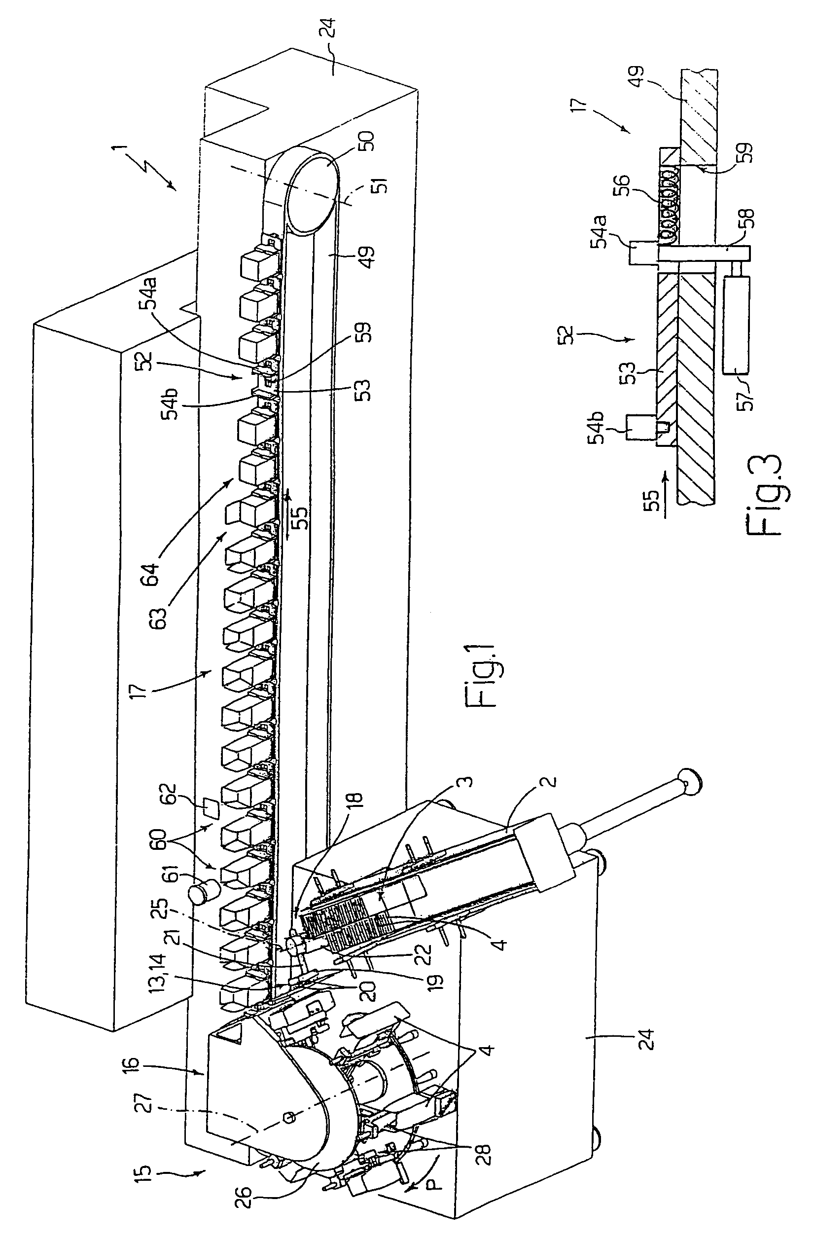
[0025]With reference to FIGS. 1 and 5, the reference numeral 1 indicates a boxing machine as a whole, which includes a magazine 2, receiving a pile 3 of tubular boxes 4.

[0026]Each of the tubular boxes 4 has, in a final, erected configuration, a parallelogram section defined by a pair of parallel walls 5, a pair of parallel walls 6, perpendicular to the walls 5, and by two open ends 7, each of which is defined, in this case, by two wings 8 connected to the walls 5 and by a flap 9, connected to one of the walls 6.

[0027]Each wall 5, 6 is connected to each adjacent wall 6, 5 along a pre-weakened folding line 10 and, likewise, each wing 8 is connected to the relative wall 5 and each flap 9 is connected to the relative wall 6 by further pre-weakened folding lines 10.

[0028]Each box 4 is arranged inside the magazine 2 in vertical position, with one of the ends 7 (from now on indicated with 7a) situated above the other end 7 (from now on indicated with 7b), and in an initial flat configurati...


PUM

PropertyMeasurementUnit
widthaaaaaaaaaa
range of movementaaaaaaaaaa
lengthaaaaaaaaaa

Abstract

In a boxing machine, a conveying and erecting device withdraws one box in an initial flattened configuration. The boxes are arranged with two overlapped layers. The conveying and erecting device gives to the withdrawn box a final erected configuration, in which the box has a parallelogram section. Subsequently, the device transfers the box, at a transferring station, into a pocket of a pocket conveyor. When in use, the pocket has a variable geometry, controlled selectively in the transferring station, to allow the box to be introduced into the pocket.

Description

BACKGROUND OF THE INVENTION[0001]The present invention relates to a method for conveying and erecting of boxes.BRIEF DESCRIPTION OF THE PRIOR ART[0002]There are known so-called boxing machines among the machines for packaging products, in particular cosmetic products.[0003]The boxing machine includes an inlet magazine, for housing a pile of tubular boxes, each of which has a plurality of walls defined by pre-weakened folding lines and is in an initial flat blank configuration, in which the box is arranged with two overlapped layers, each of which is defined by two adjacent walls of the box.[0004]The boxing machine includes also a device for withdrawing and transferring the boxes, which has a picking up member, which picks up the boxes, one by one, from the inlet magazine, engages each box on a relative wall, and feeds the boxes, one by one, to a pocket filling conveyor.[0005]The filling conveyor includes two chains, which move in respective planes, substantially parallel to each oth...

Claims


Application Information

Patent Timeline
Patent Type & Authority Patents(United States)
IPC IPC(8): B65B43/30B65B5/00B31B5/80B65B43/54
CPCB31B1/06B31B1/80B65B43/305B65B43/54B31B2201/027B31B2201/287B31B2201/289B31B2201/29B31B2203/003B31B50/004B31B50/062B31B50/80B31B50/804B31B2100/00B31B2120/30
Inventor BRINTAZZOLI, RENATO
Owner MARCHESINI GROUP SPA
Why Eureka
Try Eureka