Hybrid engine

a hybrid engine technology, applied in the direction of rotary or oscillating piston engines, rotary piston engines, engine ignition, etc., can solve the problems of significant counter-rotation force or shock pressur

Inactive Publication Date: 2009-06-23
HERRING JOHN ALEXANDER
View PDF9 Cites 11 Cited by
  • Summary
  • Abstract
  • Description
  • Claims
  • Application Information

AI Technical Summary

Benefits of technology

[0008]It is an object of the present invention to obviate or mitigate at least one disadvantage of previous Stirling-Wankel machines.

Problems solved by technology

These designs may result in significant counter-rotation force or shock pressure as the pressurized chambers pass over the inlet and outlet ports.

Method used


Image

  • Hybrid engine
  • Hybrid engine
  • Hybrid engine

Examples


Embodiment Construction

[0020]Generally, the present invention provides an Wankel rotary thermodynamic machine operating on the Carnot Cycle as a Stirling machine.

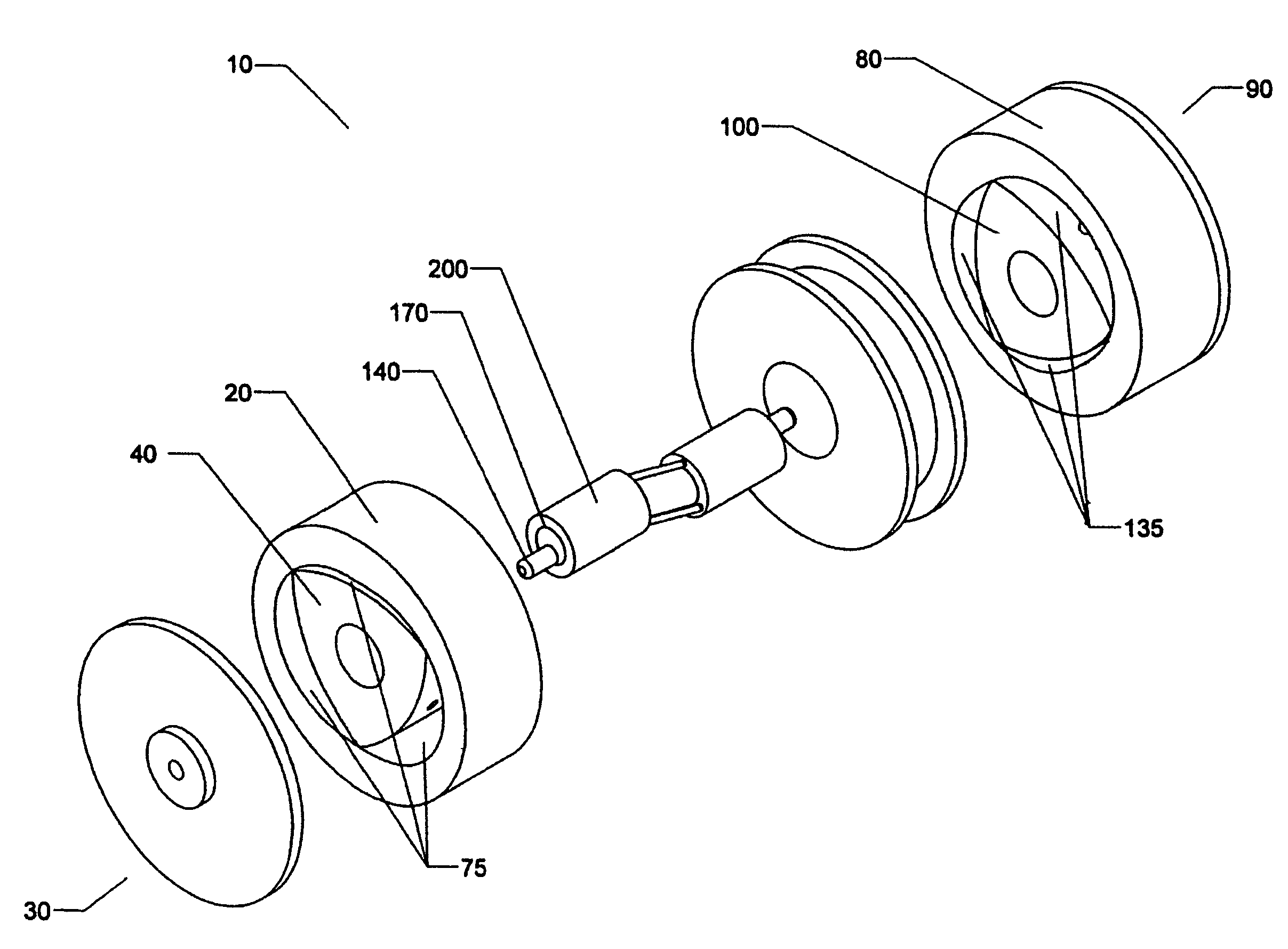
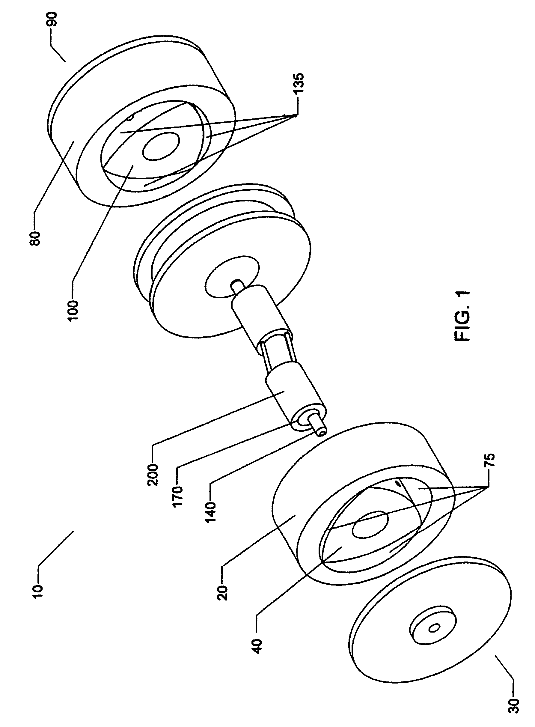
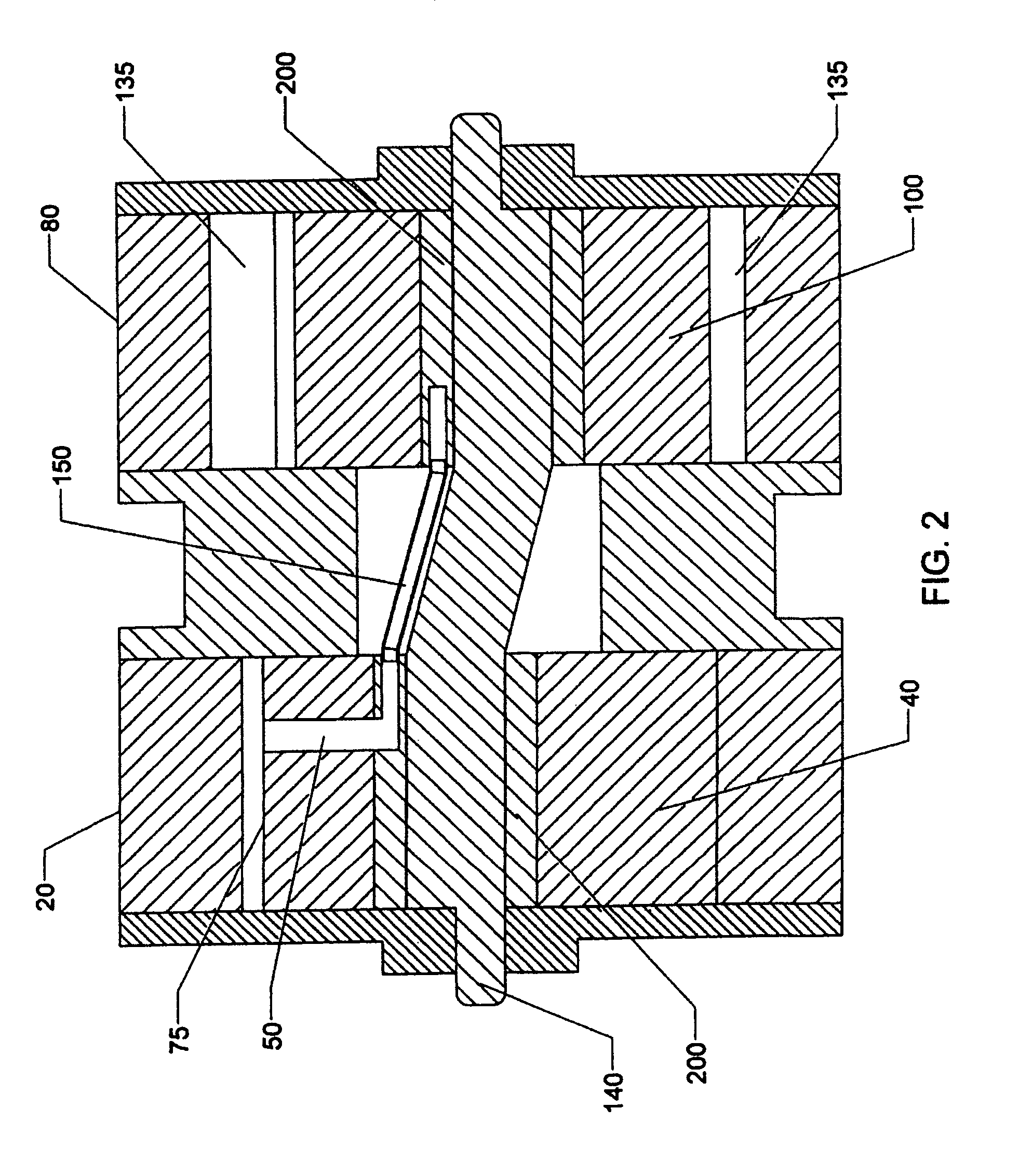
[0021]Referring generally to FIGS. 1-4, and FIG. 29, the preferred embodiment of the machine 10 has a hot side housing 20 and a cold side housing 80.

[0022]The hot side housing 20 receives heat by a heat input interface 30 and encloses a hot side rotor 40 having rotor passages 50 extending between a rotor hub 60 and a rotor face 70. Preferably, the rotor passages 50 extend through or along the side or sides of the hot side rotor 40. The hot side housing 20 encloses the hot side rotor 40 forming heated chambers 75.

[0023]The cold side housing 80 rejects heat by a heat rejection interface 90 and encloses a cold side rotor 100 having rotor passages 110 extending between a rotor hub 120 and a rotor face 130. Preferably, the rotor passages 110 extend through or along the side or sides of the cold side rotor 100. The cold side housing 80 encloses the col...


PUM


Abstract

A rotary Wankel-Stirling machine operating upon a compressible working fluid, having a rotary expander having a hot side housing with a heat input interface, a hot side rotor having rotor passages adapted to allow passage of the working fluid between the rotor hub and rotor face, heated chambers formed between the rotor face and the hot side housing, a rotary compressor having a cold side housing with a heat rejection interface, a cold side rotor having rotor passages adapted to allow passage of the working fluid between the rotor hub and rotor face, cooled chambers formed between the rotor face and the cold side housing, a shaft, adapted to rotatably couple the rotor hub of the hot side rotor and the rotor hub of the cold side rotor, the shaft having shaft passages adapted to allow passage of the working fluid between the heated chambers and the cooled chambers, and the working fluid sealed in the machine, wherein the machine operates under the Carnot cycle. The rotary Wankel-Stirling machine may be operated as an engine or a heat pump.

Description

REFERENCE TO RELATED APPLICATION[0001]This is a formal patent application based on and claiming the benefit of U.S. provisional patent application No. 60 / 676,305, filed May 2, 2005.FIELD OF THE INVENTION[0002]The present invention relates generally to rotary piston machines. More particularly, the present invention relates to a hydrid Stirling-Wankel closed-loop machine utilizing internal ducting of the working fluid. It may be used as an engine or as a heat pump.BACKGROUND OF THE INVENTION[0003]Wankel machines are well known in the art, as were first described in U.S. Pat. No. 2,988,065 to Wankel.[0004]Stirling machines are well known in the art, and operate on the basis of closed-loop compression and expansion of a compressible working fluid. The basic elements of a Stirling machine include an expander, a compressor, heat input, heat rejection, and regenerators. The regenerators act as a thermal capacitor to accept and reject heat from or to the working fluid as it transfers betwe...

Claims


Application Information

Patent Timeline
Patent Type & Authority Patents(United States)
IPC IPC(8): F01B29/10
CPCF01C1/22F01C11/004F02B73/00F02G2270/10Y02T10/17Y02T10/12
Inventor HERRING, JOHN ALEXANDER
Owner HERRING JOHN ALEXANDER
Why Eureka
Try Eureka