Method for inspecting peeling in adhesive joint

a peeling and adhesive joint technology, applied in the direction of optical apparatus testing, force measurement by measuring optical property variation, instruments, etc., can solve the problems of difficult inspection without oversight, increase in the number of steps, and difficult peeling detection, so as to achieve accurate conclusion, easy measurement, and easy inspection of peeling in the adhesive joint

Inactive Publication Date: 2009-06-23
HONDA PATENTS & TECH NORTH AMERICA
View PDF12 Cites 1 Cited by
  • Summary
  • Abstract
  • Description
  • Claims
  • Application Information

AI Technical Summary

Benefits of technology

[0012]In this arrangement, one of the two joined members is provided with a piezoelectric element (vibration means), a portion of the sensor part of the optical fiber sensor is embedded in the adhesive in the adhesive joint, and peeling in the adhesive joint is detected on the basis of the optical characteristics from the optical fiber sensor when the optical fiber sensor is irradiated with light from the light source while the member is being vibrated by the vibration means. When vibration is applied, the variation is measured in the optical characteristics from the optical fiber sensor within the determined measurement range. Vibration of the peak position of the spectrum of reflected light from the optical fiber sensor can thereby be easily measured at various temperatures, and peeling in the adhesive joint can be accurately inspected. Not only can peeling be detected at the position of the optical fiber sensor embedded in the adhesive and in proximity thereof, but peeling can also be precisely detected at positions distanced from the optical fiber sensor. Therefore, it is possible to accurately conclude whether peeling has or has not occurred. Situations can accordingly be prevented in which peeling is erroneously detected despite the fact that no peeling has occurred in practical terms, and the structure is needlessly disassembled. Specifically, maintenance costs for the structure can be reduced, and improvements in the stability of the structure can be expected.

Problems solved by technology

However, even when a skilled inspector inspects the adhesive joint with the naked eye, it is difficult to make an inspection without any oversights, and the number of steps increases.
Various sensors are used to conduct tests for evaluating the soundness of an adhesive joint, but this is impractical because of the difficulty of drawing conclusions and because of problems with the precision of inspection.
However, problems are encountered in that peeling is difficult to detect when peeling occurs in the adhesive joint at a location distanced from the sensor part embedded in the adhesive joint.
Therefore, in cases in which the aforementioned measurement window is provided and fixed in place, problems are encountered in that depending on temperature, vibration is no longer observed in the peak position of the spectrum of reflected light from the optical fiber sensor.

Method used


Image

  • Method for inspecting peeling in adhesive joint
  • Method for inspecting peeling in adhesive joint
  • Method for inspecting peeling in adhesive joint

Examples


Embodiment Construction

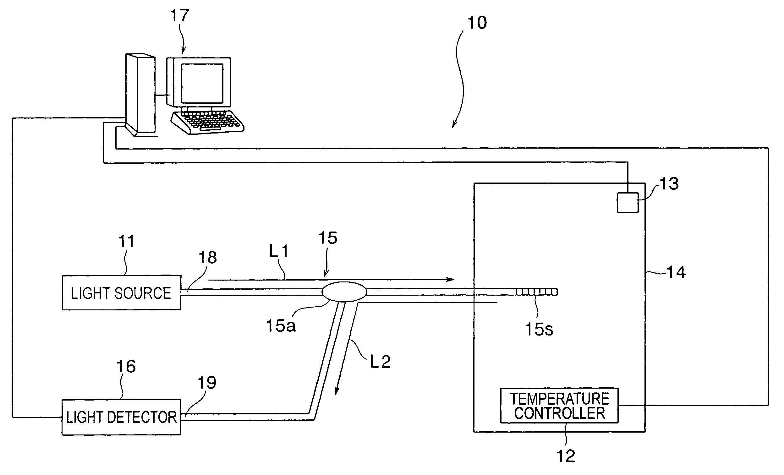
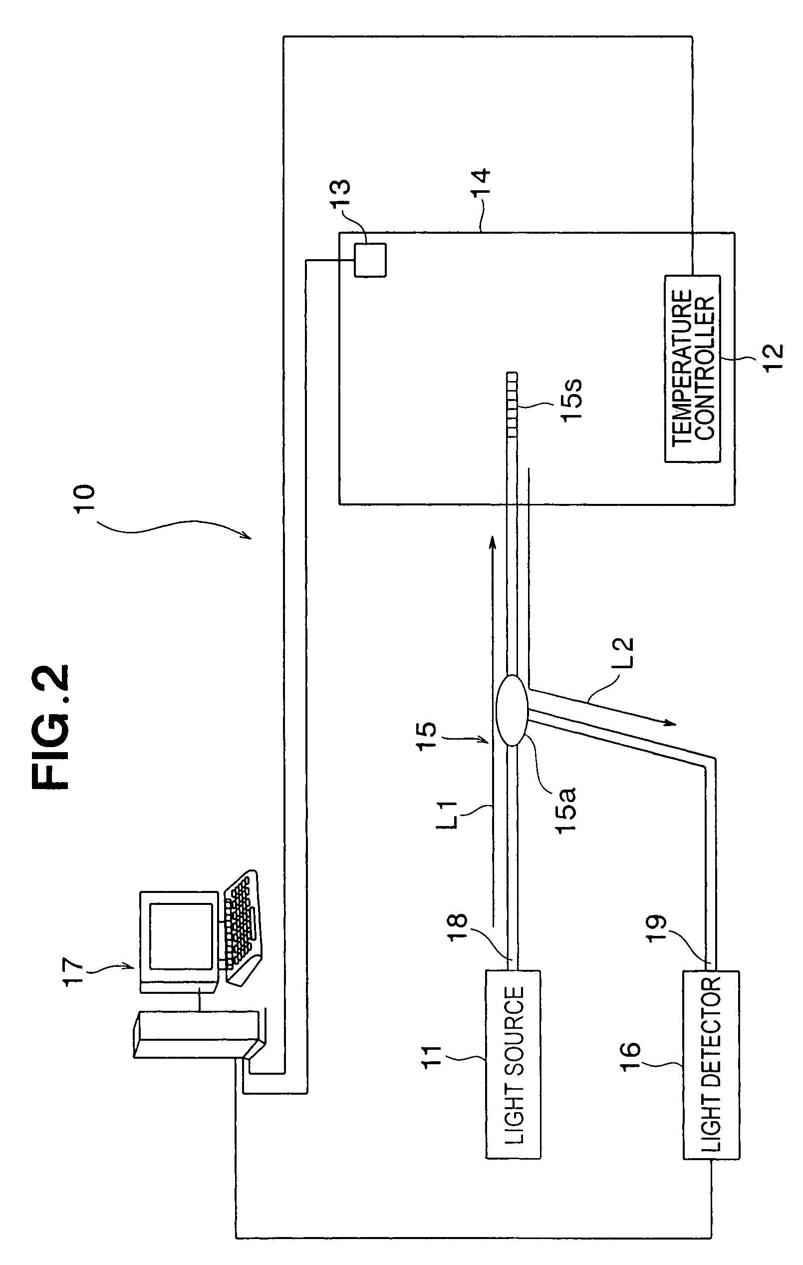
[0040]The method for inspecting peeling in an adhesive joint according to an embodiment of the present invention comprises a database creation step (step S1 shown in FIG. 1) for creating data related to the spectrum of reflected light in relation to temperature and obtained both from an optical fiber sensor whose sensor part is embedded in an adhesive in joined members composed of two members joined using the adhesive, and from an optical fiber sensor whose sensor part is not embedded in the adhesive; and a peeling inspection step (step S2 shown in FIG. 10) related to actual peeling in the adhesive joint. The database creation step and the peeling inspection step are described hereinbelow with reference to the drawings.

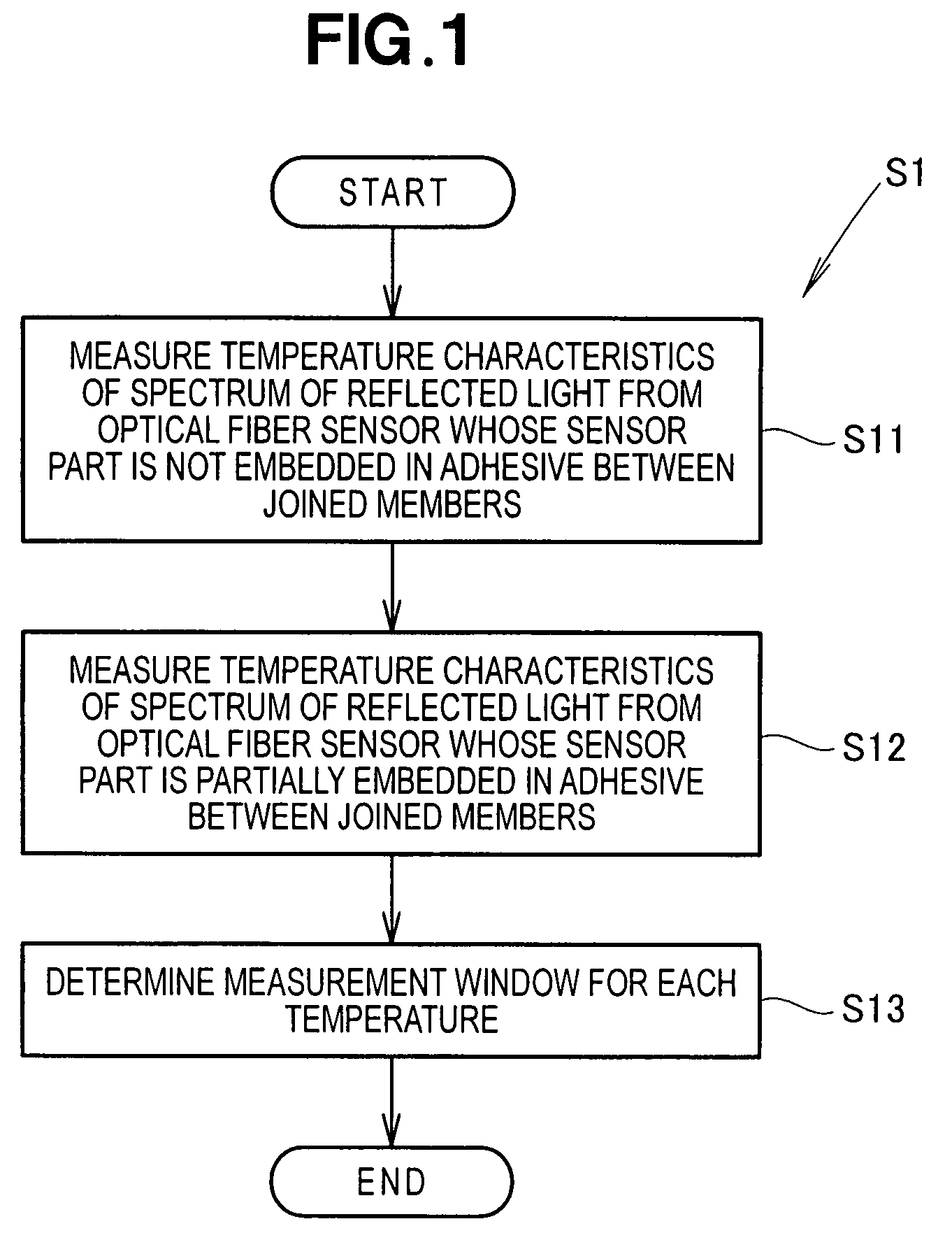
[0041]The database creation step S1 is described with reference to the flowchart in FIG. 1. The database creation step S1 has a measuring step S11 for measuring the temperature characteristics of the spectrum of reflected light from a free optical fiber sensor whose s...


PUM

PropertyMeasurementUnit
peak wavelengthaaaaaaaaaa
lengthaaaaaaaaaa
lengthaaaaaaaaaa

Abstract

A method is disclosed wherein a portion of a sensor part of an optical fiber sensor is embedded in an adhesive between two joined members, and peeling in an adhesive joint of the two members is detected on the basis of measuring optical characteristics from the optical fiber sensor when the optical fiber sensor is irradiated with light from a light source while one member is vibrated by vibration means. The method comprises the steps of determining the temperature of the two members during measurement on the basis of the optical characteristics from the sensor part exposed outside of the adhesive; determining, on the basis of the temperature determined during the measurement, the measurement range in which the optical characteristics from the optical fiber sensor are measured; and measuring the variation in the optical characteristics from the optical fiber sensor within the determined measurement range while the member is being vibrated by the vibration means.

Description

FIELD OF THE INVENTION[0001]The present invention relates to a method for inspecting peeling in an adhesive joint and, more particularly, to a method for inspecting peeling in an adhesive joint by using an optical fiber sensor.BACKGROUDN OF THE INVENTION[0002]In conventional practice an inspector inspects the soundness of an adhesive joint between two members by looking for minute cracks in the adhesive joint with the naked eye or by ultrasonic flaw detection. However, even when a skilled inspector inspects the adhesive joint with the naked eye, it is difficult to make an inspection without any oversights, and the number of steps increases. Various sensors are used to conduct tests for evaluating the soundness of an adhesive joint, but this is impractical because of the difficulty of drawing conclusions and because of problems with the precision of inspection. To resolve such problems, a technique has been devised wherein the sensor part of an optical fiber sensor is embedded in the...

Claims


Application Information

Patent Timeline
Patent Type & Authority Patents(United States)
IPC IPC(8): G01N29/04G02B6/00
CPCG01M11/086G02B6/022G01N19/04G02B6/02204
Inventor SATO, KEIICHIMURAYAMA, HIDEAKIKAGEYAMA, KAZURO
Owner HONDA PATENTS & TECH NORTH AMERICA
Why Eureka
Try Eureka