Isobutane alkylation

a technology of isobutane and alkylation, which is applied in the direction of catalyst activation/preparation, physical/chemical process catalysts, organic chemistry, etc., can solve the problems of disadvantage, alkylation catalysts, and catalyst substrates that maximize mass transfer, so as to maximize the conversion of isobutane to alkylate, reduce the effect of polymerization and high conversion ra

Inactive Publication Date: 2009-06-23
PRECISION COMBUSTION
View PDF4 Cites 33 Cited by
  • Summary
  • Abstract
  • Description
  • Claims
  • Application Information

AI Technical Summary

Benefits of technology

[0011]The present invention promotes an economically feasible use of fixed bed catalysts. In addition, the present invention offers the potential to reduce the extent of isobutane required to be recycled to a value lower than that of present commercial processes. In accordance with the present invention, a fixed bed alkylation reactor can be operated in a mass-transfer controlled regime for the desired alkylation reaction with the olefin as the limiting reactant, such that the concentration of olefin on the surface will be minimal. The rate of diffusion of olefin to the catalyst surface is maintained sufficiently low such that olefin molecules react with isobutane before encountering another olefin molecule. Thus, the probability of olefin-olefin reaction (polymerization) is greatly reduced by limiting the rate of mass transfer of olefin to the catalyst surface to a value lower than that required for significant polymerization. In other words, the alkylation reaction must be mass transfer limited.

Problems solved by technology

Thus, the rate of mass transfer to a catalytic surface in a flow channel can be controllably limited by choosing flow conditions which increase boundary layer thickness.
Catalyst substrates that maximize mass transfer, such as for example pellet bed and ultra short channel length monolithic catalysts, are disadvantageous with presently known alkylation catalysts.
However, even monolith flow channels can have an entry region where the boundary layer is minimal and the mass transfer rate much too high.
Further, because olefin polymerization tends to block catalyst sites, it is desirable that the mass transfer of olefin to the catalyst surface be sufficiently limited such that the olefin concentration on the surface is too low for significant polymerization even at the initial contact zone.

Method used


Image

  • Isobutane alkylation
  • Isobutane alkylation
  • Isobutane alkylation

Examples


Embodiment Construction

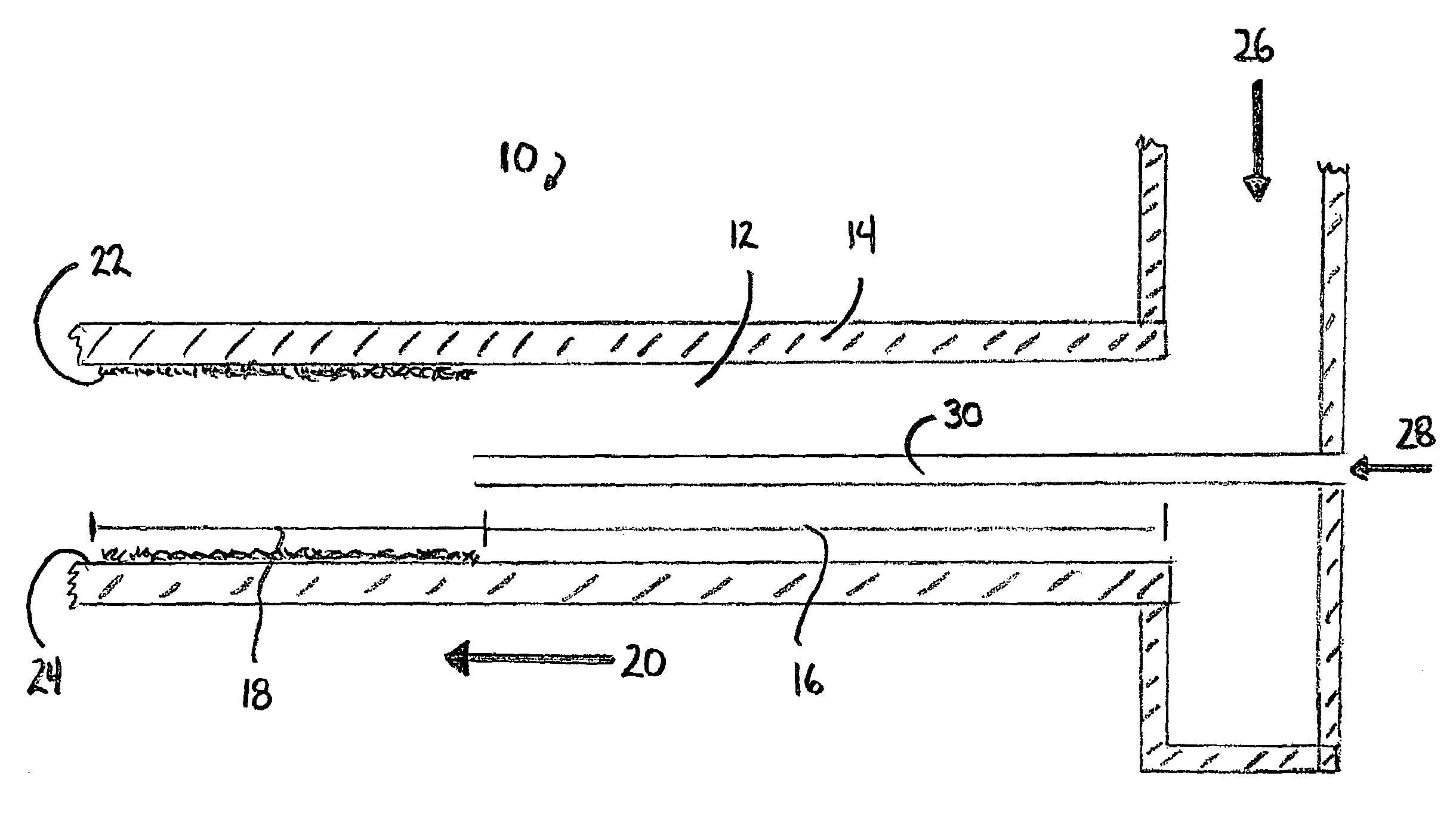
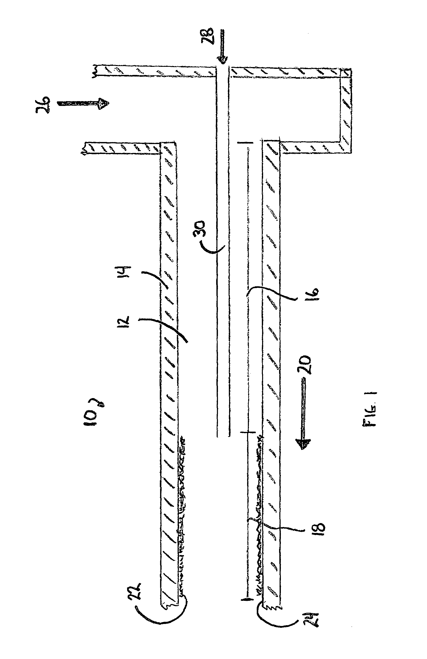
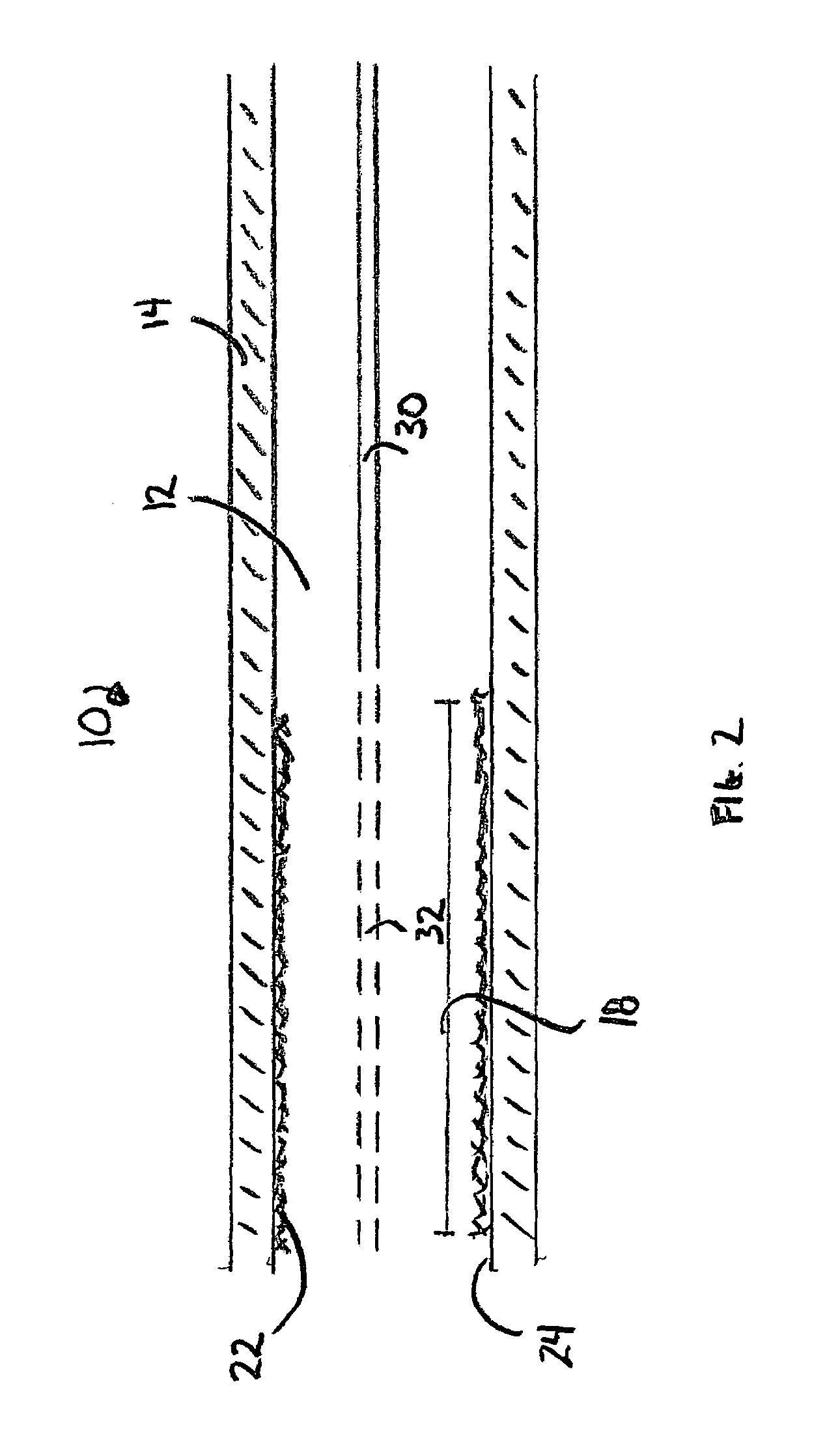
[0016]As depicted in FIG. 1, the catalytic isobutane alkylation reactor 10 comprises an alkylation reactor flow channel 12 that defines flow channel wall 14. Flow channel 12 further defines entrance region 16 and downstream region 18, wherein downstream flow 20 indicates the direction of flow through the reactor. An alkylation catalyst 22 is positioned on the inner face 24 of channel wall 14 in downstream region 18. The upstream position limit of catalyst 22 defines a transition point between entrance region 16 and downstream region 18. Catalyst 22 may be positioned on only a portion of inner face 24 of channel wall 14 in downstream region 18.

[0017]Isobutane 26 is introduced into the reactor 10 passing therethrough into entrance region 26. The isobutane flow rate is such that flow is laminar in downstream region 18. Olefin 28 is introduced into the reactor 10 through injection tube 30 and exits tube 30 along the centerline of flow channel 12. No catalyst is needed on inner face 24 i...


PUM

PropertyMeasurementUnit
molecular weightaaaaaaaaaa
concentrationaaaaaaaaaa
rate of mass transferaaaaaaaaaa

Abstract

A method for isobutane alkylation is provided using a fixed-bed catalytic alkylation reactor comprises at least one catalytic flow channel. A feed stream comprising a compound to be alkylated is passed into a flow channel having an alkylation catalyst positioned on at least a portion of the flow channel inner surface in the flow channel downstream region. Olefin is injected into the feed stream at a point beyond a flow channel entrance region whereby the olefin contacts the alkylation catalyst by diffusion to the flow channel inner surface thereby reacting the compound with the olefin and produces an alkylate product.

Description

CROSS-REFERENCE TO RELATED APPLICATION[0001]This application claims the benefit of U.S. Provisional Application No. 60 / 569,599 filed May 10, 2004. This application also is a continuation-in-part of U.S. patent application Ser. No. 11 / 115,512; filed Apr. 27, 2005, and incorporated herein by reference.BACKGROUND OF THE INVENTION[0002]1. Field of the Invention[0003]The present invention relates to a method for catalytic isobutane alkylation. More particularly, the present invention is directed to a catalytic isobutane alkylation process that is advantageous for the alkylation of isobutane or benzene, as well as other compounds.[0004]2. Description of the Related Art[0005]Isobutane alkylation by reaction with an olefin is an important refinery process producing a high-octane alkane hydrocarbon product used to produce high-octane gasoline of low aromatic content. Commercial alkylation processes rely on use of either hydrogen fluoride or sulfuric acid catalyst systems. Unfortunately, both...

Claims


Application Information

Patent Timeline
Patent Type & Authority Patents(United States)
IPC IPC(8): C07C2/54C07C2/58B01J4/00B01J19/24B01J37/02C07C2/66C07C2/68
CPCB01J4/00B01J19/2485B01J37/0246C07C2/58C07C2/66
Inventor PFEFFERLE, WILLIAM C.
Owner PRECISION COMBUSTION
Why Eureka
Try Eureka