Triple polarized clover antenna with dipoles

a clover antenna and dipole technology, applied in the direction of polarised antenna unit combinations, antenna feed intermediates, antennas, etc., can solve the problems of large arrays that are unsuitable for e.g. hand-held terminals, difficult to match properly, and large space requirements, etc., to achieve the effect of easy manufacturing

Active Publication Date: 2009-06-23
TELEFON AB LM ERICSSON (PUBL)
View PDF4 Cites 8 Cited by
  • Summary
  • Abstract
  • Description
  • Claims
  • Application Information

AI Technical Summary

Benefits of technology

[0017]A triple polarized antenna made in planar technique is made possible, avoiding space consuming antenna arrangements.
[0018]A triple polarized antenna which is easy to manufacture is obtained.

Problems solved by technology

If more than two orthogonal polarizations are to be utilized for one antenna, it is necessary that it is used in a so-called rich scattering environment having a plurality of independent propagation paths, since it otherwise is not possible to have benefit from more than two orthogonal polarizations.
This, however, results in big arrays that are unsuitable for e.g. hand-held terminals.
It has then been suggested to use three orthogonal dipoles for a MIMO antenna with three ports, but such an antenna is complicated to manufacture and requires a lot of space when used at higher frequencies, such as those used for the MIMO system (about 2 GHz).
Said small loop antenna is, however, quite narrow-banded and hence difficult to match properly since it has a high reactive resistance and a low resistive resistance.
Further, such a small loop antenna is considerably smaller than the adjacent dipole antennas, resulting in an awkward construction.
There is thus a problem with the antenna arrangement according to US 2002 / 0113748, since the loop element has to be very small in order to function as a sufficient approximation of a constant current loop element.

Method used


Image

  • Triple polarized clover antenna with dipoles
  • Triple polarized clover antenna with dipoles
  • Triple polarized clover antenna with dipoles

Examples


first embodiment

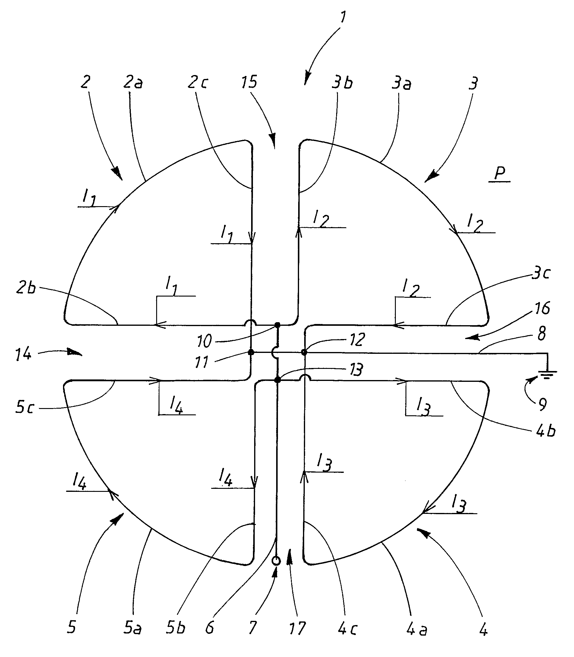
[0058]In the previously described first embodiment, the four-leaf clover antenna and the first and second dipoles are made by a bent wire, for example a copper wire. Any other conducting material will perform the function of the present invention.

second embodiment

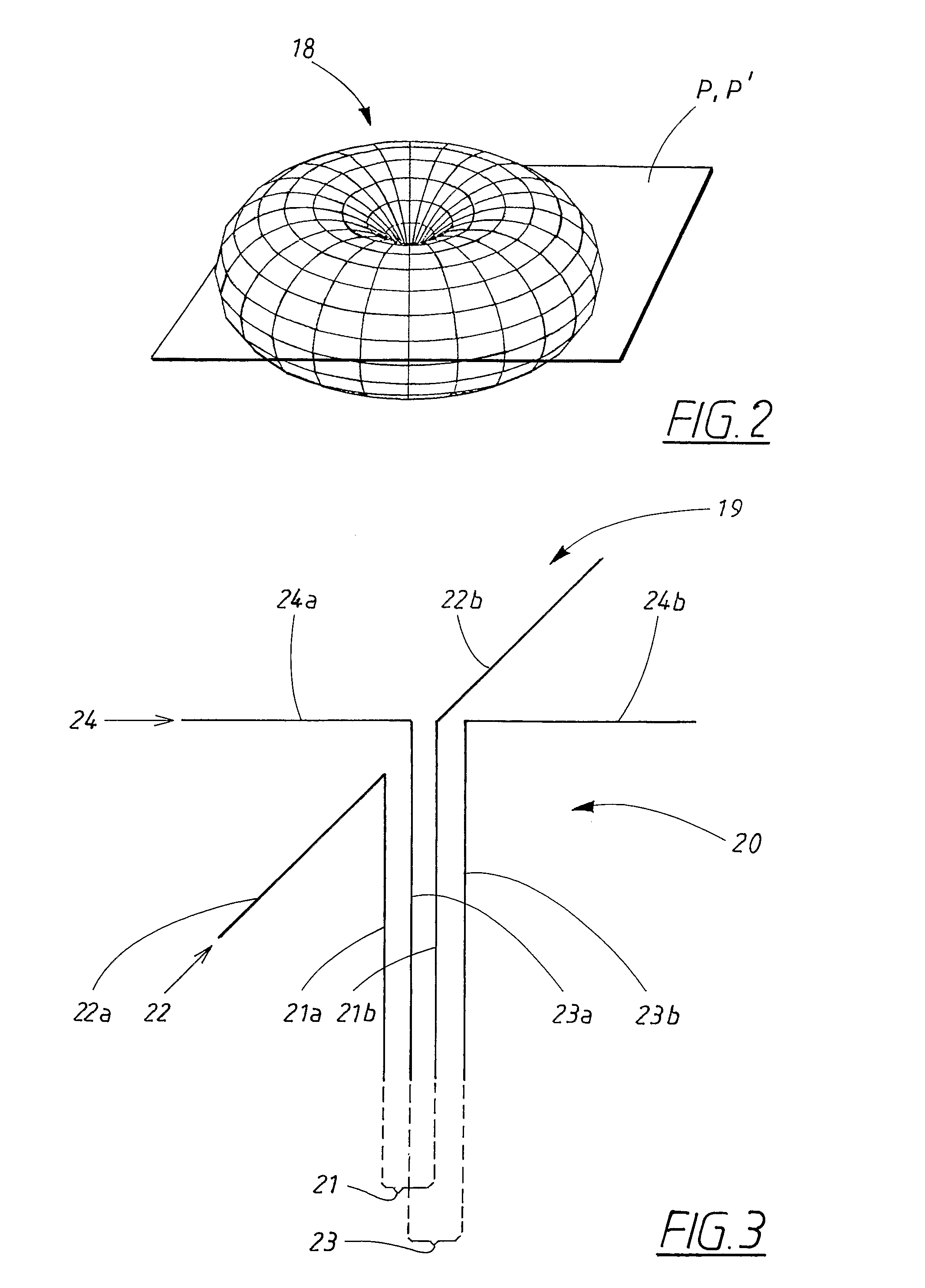
[0059]In a second embodiment, the four-leaf clover antenna and the first and second dipoles are made in planar techniques, constituting a microstrip antenna. As shown schematically in FIG. 7, the triple-mode antenna according to the present invention then comprises a first 32, second 33, third 34 and fourth 35 copper-clad dielectric laminate, for example a Teflon-based laminate, placed on top of each other. Be removing the copper, different conducting structures may be formed on the laminates 32, 33, 34, 35. Removal of copper may be made by means etching, or, alternatively, milling.

[0060]In FIG. 7, the first 32, second 33, third 34 and fourth 35 laminates, each one having a first 36, 37, 38, 39 and second 40, 41, 42, 43 side, are shown from the side, forming a sandwich structure. The sandwich structure has a top 44, a bottom 45 and a first 46, second 47 and third 48 intermediate section, where each intermediate section 46, 47, 48 is formed between two adjacent laminates.

[0061]On the...


PUM


Abstract

The present invention relates to an antenna arrangement comprising a constant current electrical loop, which is arranged to provide a first essentially toroid-shaped radiation pattern, where the antenna arrangement further comprises a first and a second electrical dipole. The electrical dipoles are arranged essentially orthogonal to each other, and are arranged to provide a second and third essentially toroid-shaped radiation pattern which each is essentially orthogonal to the other and to the first essentially toroid-shaped radiation pattern. The constant current electrical loop comprises at least two current path parts, where a current can be applied to each one of the parts, so that the current in each one of the parts essentially will be in phase with each other.

Description

TECHNICAL FIELD[0001]The present invention relates to an antenna arrangement comprising means for providing an approximation of a constant current electrical loop, which approximation of a constant current electrical loop is arranged to provide a first essentially toroid-shaped radiation pattern, where the antenna arrangement further comprises a first and a second electrical dipole, which electrical dipoles are arranged essentially orthogonal to each other, and are arranged to provide a second and third essentially toroid-shaped radiation pattern which each is essentially orthogonal to the other and to the first essentially toroid-shaped radiation pattern.BACKGROUND ART[0002]The demand for wireless communication systems has grown steadily, and is still growing, and a number of technological advancement steps have been taken during this growth. In order to acquire increased system capacity for wireless systems by employing uncorrelated propagation paths, MIMO (Multiple Input Multiple...

Claims


Application Information

Patent Timeline
Patent Type & Authority Patents(United States)
IPC IPC(8): H01Q21/00H01Q21/26
CPCH01Q9/16H01Q21/26
Inventor MANHOLM, LARSHARRYSSON, FREDRIKMEDBO, JONAS
Owner TELEFON AB LM ERICSSON (PUBL)
Why Eureka
Try Eureka