Power tool

a technology of power tools and supports, applied in the field of power tools, can solve the problems of inability to continuously variable manual rapid adjustment, inability to adjust manually, and the grip region of the support foot is markedly less stable than a support foot of that kind of metal

Inactive Publication Date: 2009-06-30
ROBERT BOSCH GMBH
View PDF19 Cites 27 Cited by
  • Summary
  • Abstract
  • Description
  • Claims
  • Application Information

AI Technical Summary

Benefits of technology

[0003]Accordingly, it is an object of the present invention to provide a power tool which eliminates the disadvantages of the prior art.

Problems solved by technology

From German Patent DE 196 37 690 C2, a power tool designed as a top spindle molder with cutting depth adjustment is known, which permits relatively safe, convenient adjustment of the cutting depth, but a continuously variable manual rapid adjustment is not possible, and the grip region of the support foot, while it is of plastic and is nonslip, is nevertheless markedly less stable than a support foot of that kind of metal, such as aluminum.

Method used


Image

  • Power tool
  • Power tool
  • Power tool

Examples


Embodiment Construction

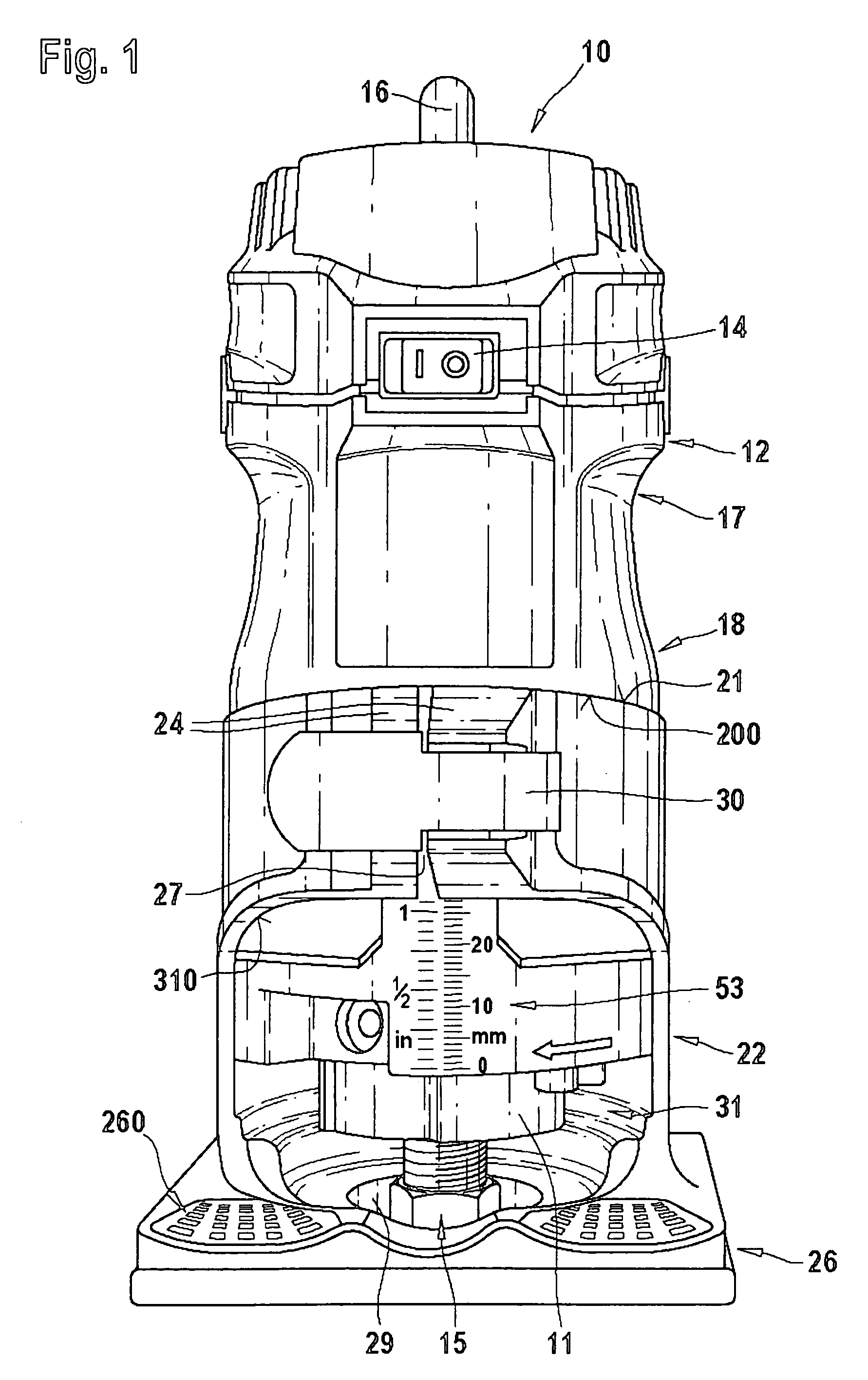
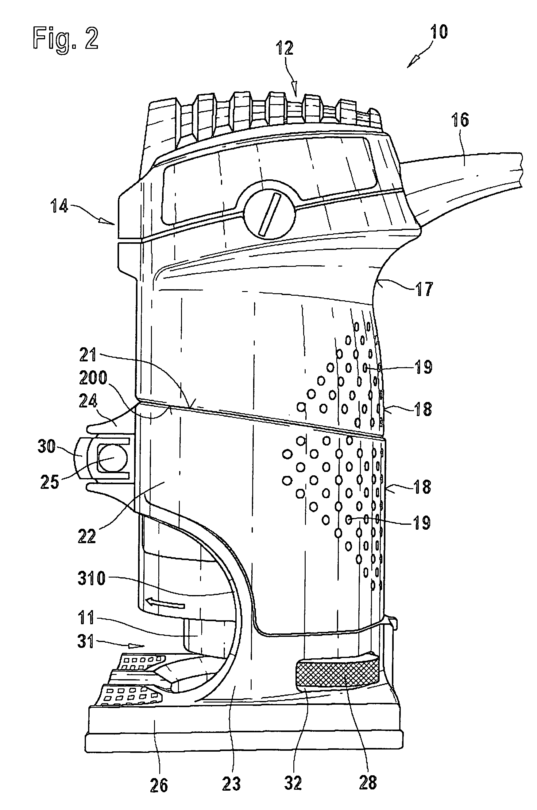
[0038]As an electrically powered top spindle molder, which comprises a housing 12 that has a push button 14 at the front for turning it on and off, and from whose lower free end 11 a rotating tool 15 for machining of workpieces protrudes.

[0039]The cylindrical housing 12, in the uppermost quarter of its length, has a waist 17, which can easily be grasped with one hand and, with its radial projection conforms in an axially supportive way to the hand holding it. The lower half of the housing 12 has a slightly smaller outer diameter than the upper region, and with the smaller diameter forms a collar 20 (FIG. 3), which can be slid in telescoping fashion into a hollow-cylindrical support foot 22. The transition between the collar 20 and the upper region of the housing 12 forms a projection or an edge 200 that can be felt.

[0040]This edge 200, located between the collar 20 and the region of the housing 12 located above it and having the larger diameter, extends rearward—matching the upper e...


PUM

PropertyMeasurementUnit
diameteraaaaaaaaaa
thicknessaaaaaaaaaa
thicknessaaaaaaaaaa

Abstract

A power tool has a housing, a tool, and a guard embracing the tool that is coupleable to the housing and axially adjustable relative, so that it is safer to handle because the guard is designed as a support foot and on its outside has a jacket piece of plastic with a nonslip, rough outer surface.

Description

BACKGROUND OF THE INVENTION[0001]The present invention is based on a power tool.[0002]From German Patent DE 196 37 690 C2, a power tool designed as a top spindle molder with cutting depth adjustment is known, which permits relatively safe, convenient adjustment of the cutting depth, but a continuously variable manual rapid adjustment is not possible, and the grip region of the support foot, while it is of plastic and is nonslip, is nevertheless markedly less stable than a support foot of that kind of metal, such as aluminum.SUMMARY OF THE INVENTION[0003]Accordingly, it is an object of the present invention to provide a power tool which eliminates the disadvantages of the prior art.[0004]In keeping with these objects and with others which will become apparent hereinafter, one feature of the present invention resides, briefly stated, in a power tool, comprising a housing; a tool; guard means embracing said tool, said guard means being couplable to said housing and axially adjustable r...

Claims


Application Information

Patent Timeline
Patent Type & Authority Patents(United States)
IPC IPC(8): B27C5/10
CPCB27C5/10Y10T409/306608B23Q16/10B25F5/02
Inventor KAGELER, SVENBRAUN, MARCOJALIL, REZWAN ISKANDARAHMAD, MOHAMED ZAIDI
Owner ROBERT BOSCH GMBH
Why Eureka
Try Eureka