Reader/writer, optical transceiver module, and cable system

a technology of optical transceiver and cable system, which is applied in the direction of cables, instruments, and equipment for laying cables, can solve the problem of taking a long time to connect those cables, and achieve the effect of speedily recognizing corresponden

Active Publication Date: 2009-06-30
LUMENTUM JAPAN INC
View PDF6 Cites 102 Cited by
  • Summary
  • Abstract
  • Description
  • Claims
  • Application Information

AI Technical Summary

Benefits of technology

[0006]The present invention has been made in view of the above-mentioned circumstances, and therefore, it is an object of the invention to provide a technique capable of speedily recognizing a correspondence between one end and the other end of a cable when a plurality of cables is laid.
[0011]According to the present invention, it is possible to speedily recognize the correspondence between one end and the other end of a cable when a plurality of cables is laid. Further, it is possible to write necessary data into an RF tag from one end of the cable through the cable even when the RF tag is provided to the other end of the cable, without moving all the way to the place where the other end of the cable is laid.

Problems solved by technology

Therefore, it is necessary to confirm one by one the correspondence between one end and the other end of each of the cables, which may lead to a case where it takes a long time to connect those cables.

Method used


Image

  • Reader/writer, optical transceiver module, and cable system
  • Reader/writer, optical transceiver module, and cable system
  • Reader/writer, optical transceiver module, and cable system

Examples


first embodiment

[0024]Hereinafter, a first embodiment according to the present invention is explained.

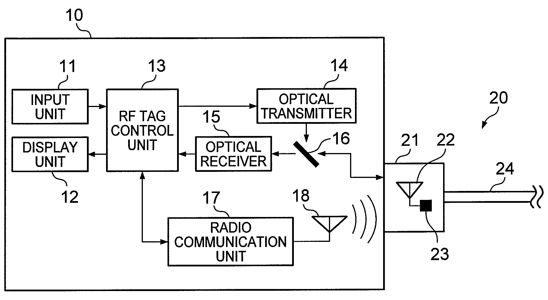
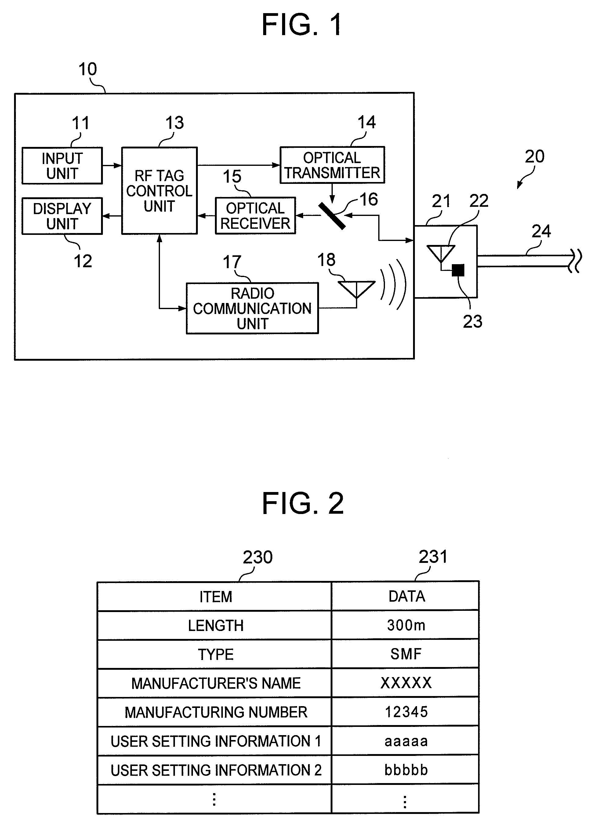
[0025]FIG. 1 is a block diagram illustrating a configuration of a reader / writer 10 according to the first embodiment of the present invention. The reader / writer 10 includes an input unit 11, a display unit 12, an RF tag control unit 13, an optical transmitter 14, an optical receiver 15, an optical splitter 16, a radio communication unit 17, and an antenna 18. The reader / writer 10 is used while being connected to a fiber-optic cable 20 which transmits an optical signal.

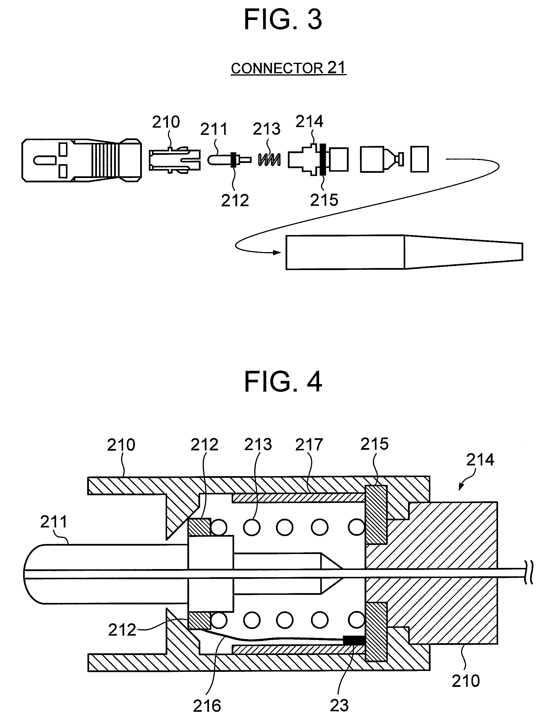
[0026]The fiber-optic cable 20 is provided with a connector 21 at both ends thereof. The connector 21 accommodates an antenna 22 and an IC chip 23. The IC chip 23 is driven by electric power generated by a radio wave received through the antenna 22. The IC chip 23 has a function of performing radio communication through the antenna 22 in compliance with the specifications of an RF tag (for example, ISO / IEC 18000-3) and a memory or the...

second embodiment

[0048]Hereinafter, a second embodiment according to the present invention is explained.

[0049]FIG. 6 is a block diagram illustrating a configuration of an optical transmission device 40 according to the second embodiment of the present invention. The optical transmission device 40 includes an input unit 41, a display unit 42, a control unit 43, a network interface 44, a plurality of optical transceiver modules 50. The fiber-optic cable 20 according to this embodiment has a configuration similar to that of the first embodiment, and therefore an explanation thereof is omitted.

[0050]Each of the optical transceiver modules 50 converts an optical signal received through the fiber-optic cable 20 into an electric signal and sends the electric signal to the network interface 44. The optical transceiver module 50 also converts an electric signal received from the network interface 44 into an optical signal and transmits the optical signal through the fiber-optic cable 20.

[0051]Also, each of t...

third embodiment

[0084]FIG. 11 is a block diagram illustrating a configuration of a reader / writer 70 according to the present invention. The reader-writer 70 includes an input unit 71, a display unit 72, an RF tag control unit 73, a transmitter 74, a switch 75, a receiver 76, a radio communication unit 77, and an antenna 78. The reader / writer 70 is used while being connected to a cable 80 which transmits an electric signal.

[0085]The cable 80 is formed by covering core wire 81 made of a conductive material such as metal with coating 84 made of a nonconductive material such as vinyl. An antenna 82 and an IC chip 83 are provided to each end of the cable 80. The RF tag control unit 73 is driven by electric power generated by a radio wave received through the display unit 72. The RF tag control unit 73 has a function of performing radio communication through the display unit 72 in compliance with the specifications of an RF tag (for example, ISO / IEC 18000-3) and a memory or the like which stores data ext...


PUM


Abstract

A reader / writer is provided which is capable of speedily recognizing a correspondence between one end and the other end of a fiber-optic cable when a plurality of fiber-optic cables is laid. The reader / writer according to the present invention reads, on receiving through the fiber-optic cable a signal that is an instruction to read data from a RF tag mounted to an end of the fiber-optic cable, data from the RF tag through radio communication, and transmits the read data through the fiber-optic cable. Also, on receiving through the fiber-optic cable a signal that is an instruction to write data into the RF tag and a signal indicating the write data, the reader / writer writes the write instruction and the write data into the RF tag through radio communication.

Description

[0001]This application relates to and claims priority from Japanese Patent Application No. 2006-170886, filed on Jun. 21, 2006, the entire disclosure of which is incorporated herein by reference.BACKGROUND OF THE INVENTION[0002]The present invention relates to a reader / writer (reading and writing device) for a noncontact RF (Radio Frequency) tag provided to a fiber-optic cable or to an electrical cable.[0003]Japanese Patent Laid-open Publication No. 2005-216698 (hereinafter, referred to as Patent Document 1) discloses a technique in which an RF tag is provided to a plug provided at an end of a cable and also to an adaptor which connects the plug, and unique information is recorded on each RF tag. According to the technique of Patent Document 1, there is created a table which shows a correspondence between a plug and an adapter to be connected to each other based on the information written into each RF tag. During an actual connecting operation, information recorded in a plug and inf...

Claims


Application Information

Patent Timeline
Patent Type & Authority Patents(United States)
IPC IPC(8): G06K7/00G06K19/06G06K7/08G08B13/14H04Q5/22G02B6/00G02B6/36G02B6/38G02B6/42G02B6/46H02G1/06H04B10/40H04B10/50H04B10/524H04B10/556H04B10/60
CPCH04B10/40H04W4/18
Inventor TOKITA, SHIGERUMATSUE, HIROOCLEITUS, ANTONYKIKUCHI, TOMONAO
Owner LUMENTUM JAPAN INC
Why Eureka
Try Eureka