Backlight device and liquid crystal display

a backlight device and liquid crystal display technology, which is applied in the direction of lighting and heating devices, lighting device details, instruments, etc., can solve the problems of limited light that can be emitted by one led and extremely difficult to secure sufficient brightness, so as to increase the number of light emitting devices and increase the light amount

Active Publication Date: 2009-06-30
SHARP KK
View PDF12 Cites 21 Cited by
  • Summary
  • Abstract
  • Description
  • Claims
  • Application Information

AI Technical Summary

Benefits of technology

[0014]The object of the present invention is to solve the above-described problems, and to provide a backlight apparatus, which can increase a light amount by increasing the number of light emitting devices that can be disposed, and a liquid crystal display using the same.
[0019]Thus, according to the backlight apparatus of the present invention, since a pitch between the light emitting devices in the thickness direction of the light guide plate can be shorten, it is possible increase the light amount by increasing the number of the light emitting devices that can be disposed.

Problems solved by technology

Moreover, an amount of light that can be emitted by one LED is limited.
Thus, in the case where the sidelight-type backlight apparatus that has the conventional LEDs as the light sources is applied to a liquid crystal display that has a large-sized screen, it is extremely difficult to secure sufficient brightness.

Method used


Image

  • Backlight device and liquid crystal display
  • Backlight device and liquid crystal display
  • Backlight device and liquid crystal display

Examples


embodiment 1

Preferred Embodiment 1

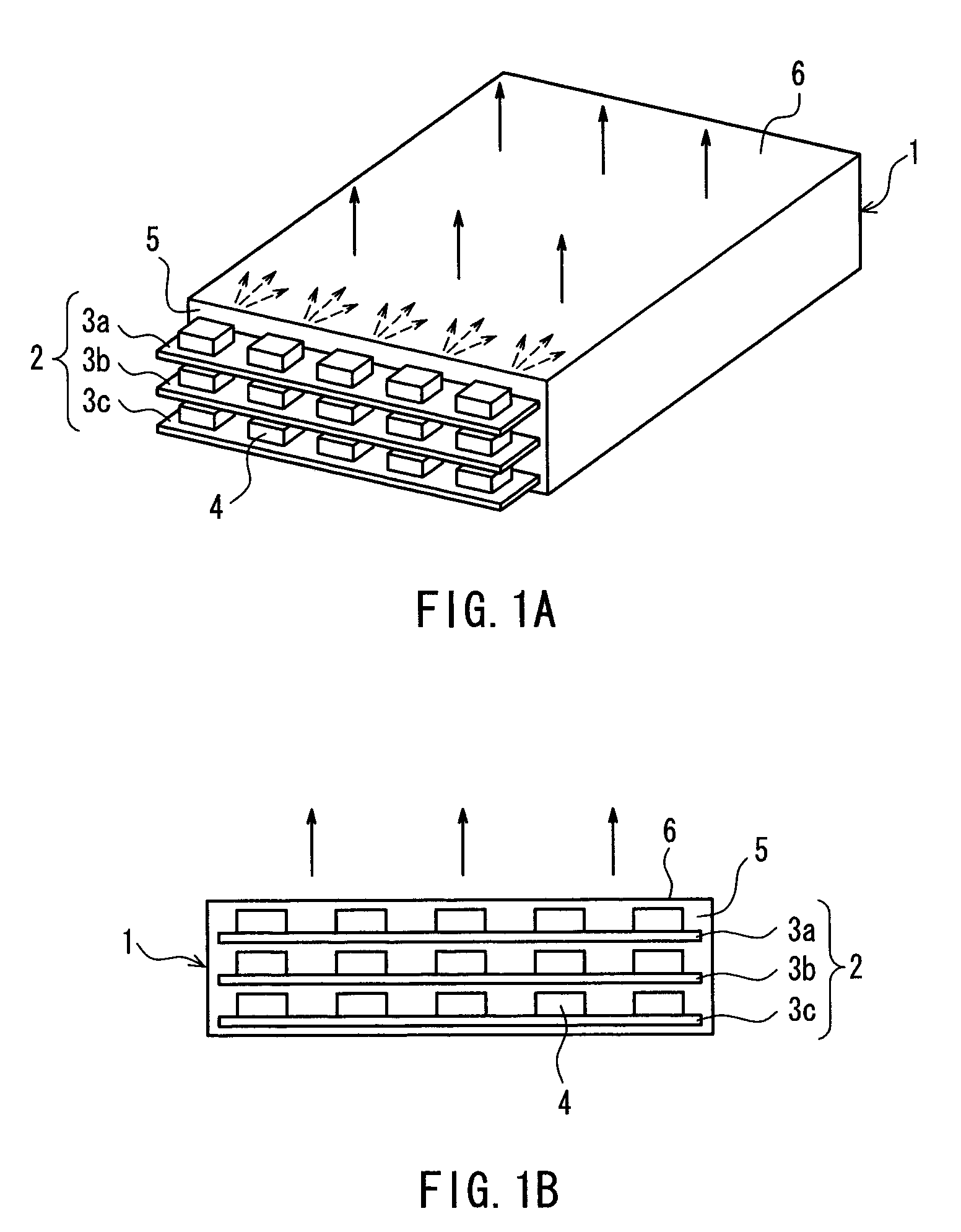
[0045]A backlight apparatus according to Embodiment 1 of the present invention will be described below with reference to FIGS. 1 and 2. FIG. 1 is a view schematically showing a structure of a first example of the backlight apparatus according to Embodiment 1 of the present invention, FIG. 1A is a perspective view thereof, and FIG. 1B is a side view thereof seen from an incident face side.

[0046]As shown in FIG. 1, the backlight apparatus of the present embodiment is a sidelight-type backlight apparatus. The backlight apparatus is provided with a light guide plate 1 and a light source unit 2. In the example of FIG. 1, the light guide plate 1 is a plate body having two rectangular-shaped main faces and four rectangular-shaped lateral faces, and one of the lateral faces serves as an incident face 5. Moreover, one of the main faces on one side of the light guide plate 1 (on an upper side in the figure) serves as a light exit face 6.

[0047]Moreover, as shown in FIG. 1...

embodiment 2

Preferred Embodiment 2

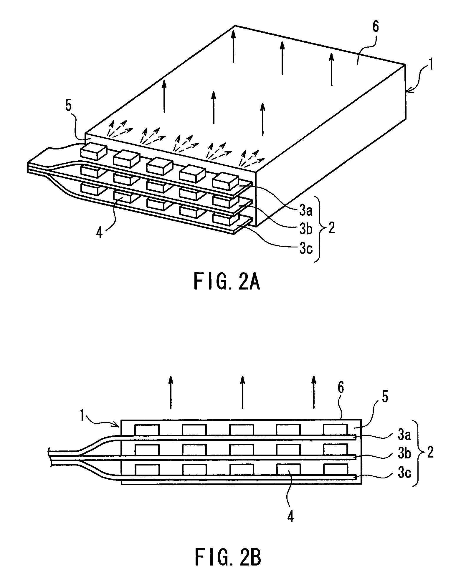
[0066]Next, a backlight apparatus according to Embodiment 2 of the present invention will be described with reference to FIG. 4. FIG. 4 is a view schematically showing a structure of the backlight apparatus according to Embodiment 2 of the present invention, FIG. 4A is a perspective view thereof, and FIG. 4B is a side view thereof seen from an incident face side.

[0067]As shown in FIG. 4, the backlight apparatus of Embodiment 2 is also a sidelight-type backlight apparatus similarly to that of Embodiment 1. Moreover, the backlight apparatus of Embodiment 2 is also provided with the light source unit 2 on the incident face 5 side of the light guide plate 1, similarly to that of Embodiment 1.

[0068]However, as shown in FIG. 4, the backlight apparatus of Embodiment 2 is provided with heat sink plates 8 between the substrate 3a and the substrate 3b adjacent to the substrate 3a that constitute the light source unit 2, and between the substrate 3b and the substrate 3c t...

embodiment 3

Preferred Embodiment 3

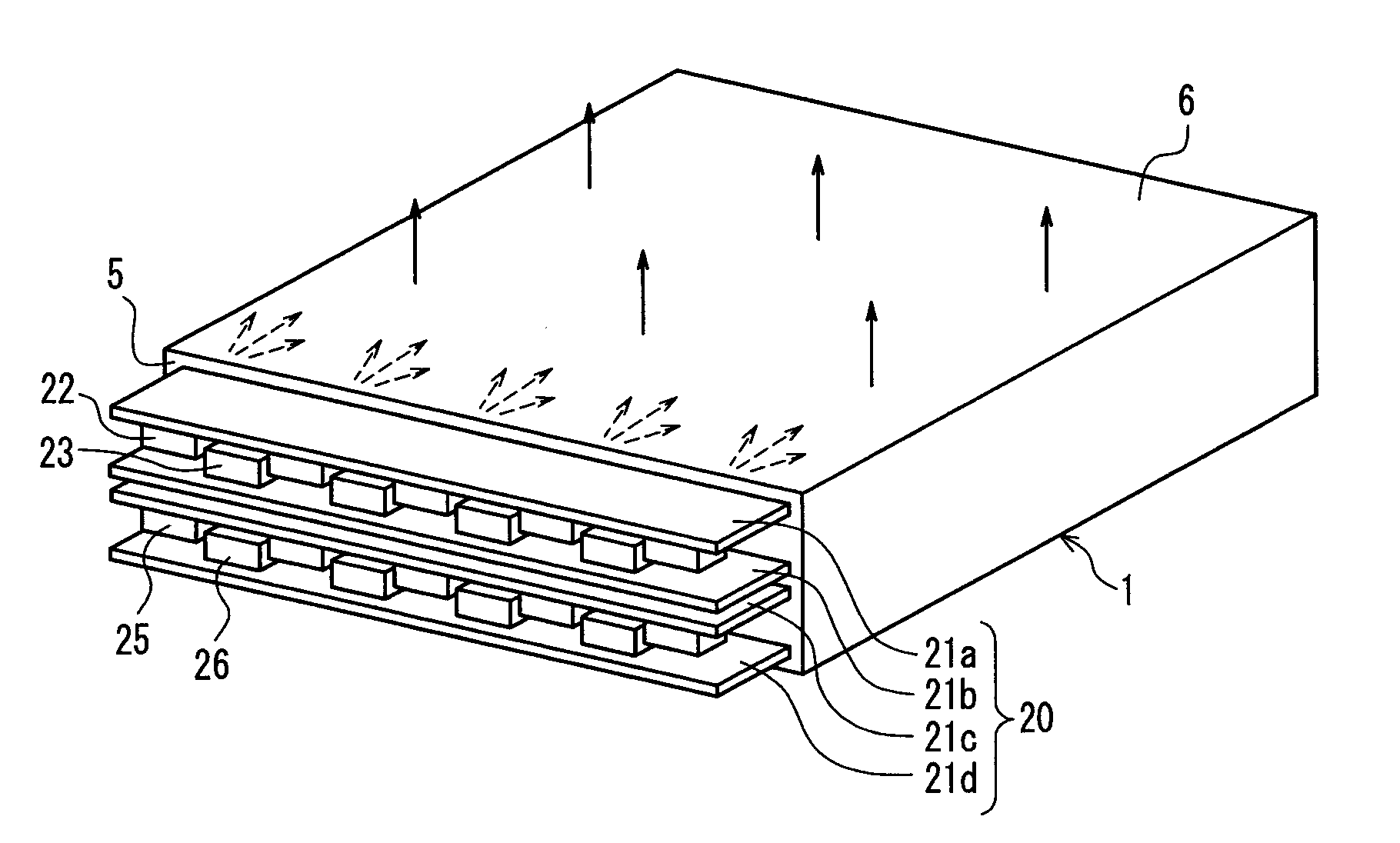
[0073]Next, a backlight apparatus according to Embodiment 3 of the present invention will be described with reference to FIGS. 5 to 7. FIG. 5 is a view schematically showing a structure of a first example of the backlight apparatus according to Embodiment 3 of the present invention, FIG. 5A is a perspective view thereof, and FIG. 5B is a side view thereof seen from an incident face side.

[0074]As shown in FIG. 5, the backlight apparatus of Embodiment 3 is also a sidelight-type backlight apparatus similarly to that of Embodiment 1. Moreover, the backlight apparatus of Embodiment 3 is also provided with a light source unit 20 on the incident face 5 side of the light guide plate 1, similarly to that of Embodiment 1.

[0075]However, as shown in FIG. 5, in the backlight apparatus of Embodiment 3, two substrates 21a and 21b that are adjacent to each other in the longitudinal direction are disposed such that mounting faces thereof face each other. Moreover, a plurality o...


PUM


Abstract

A backlight apparatus of a sidelight type includes a light guide plate having an incident face on a lateral face and a light source unit having a plurality of substrates. The plurality of the substrates are respectively disposed on the incident face side of the light guide plate such that each of substrate faces of the substrates is parallel with a light exit face of the light guide plate, and the substrates are adjacent to one another in a thickness direction of the light guide plate. A plurality of light emitting devices that emit light along the substrate faces are mounted in columns on each of the substrate faces of the plurality of the substrates such that emitting directions of the light emitting devices are directed to the incident face.

Description

BACKGROUND OF THE INVENTION[0001]1. Field of the Invention[0002]The present invention relates to a sidelight-type backlight apparatus for a liquid crystal display, and a liquid crystal display using the same.[0003]2. Description of the Related Art[0004]Recently, the reduction of thicknesses, sizes and weights of liquid crystal displays, the increases of their brightness and the savings of their power consumption have been demanded. In order to respond to these demands, a backlight apparatus using a light emitting diode (hereinafter, simply called an “LED”) as a light source, instead of using a fluorescent lamp, has been developed. A backlight apparatus using an LED as a light source can reduce its size and can save its power consumption because of its structure, compared with the case of using a fluorescent lamp. Moreover, the backlight apparatus does not contain mercury that is contained in a fluorescent lamp, and thus has excellent environmental friendliness. Thus, the backlight a...

Claims


Application Information

Patent Timeline
Patent Type & Authority Patents(United States)
IPC IPC(8): F21V7/04
CPCG02B6/0068G02B6/0021G02B6/0028G02B6/0046
Inventor TANABE, TAKAYOSHI
Owner SHARP KK
Why Eureka
Try Eureka