Annular support for rolling bearings

a technology of rolling bearings and support rods, which is applied in the direction of bearings, shafts, motors, etc., can solve the problems of reducing the mechanical uniformity of elastomeric materials, and the inability to achieve uniform mechanical properties in time, so as to reduce axial friction and reduce tangential friction. , the effect of effectively restraining the vibration transmitted

Inactive Publication Date: 2009-06-30
VARIAN SPA
View PDF25 Cites 37 Cited by
  • Summary
  • Abstract
  • Description
  • Claims
  • Application Information

AI Technical Summary

Benefits of technology

[0028]It is therefore the main object of the present invention to overcome the above drawbacks, by providing an annular support for rolling bearings, which is capable of effectively restraining the vibrations transmitted by the bearing or rotating shaft the support is associated with, and which exhibits a reduced axial friction and a considerable tangential friction with the surface of the ring of said bearing or of said shaft.
[0030]Thanks to the provision of the plates joining the inner and outer cylindrical shells and acting as resilient members, vibrations can be effectively restrained.
[0031]Advantageously, by interposing one or more pads, for instance made of silicone rubber, between the resilient plates of the support, the damping support action can be increased.

Problems solved by technology

Another source of shaft vibrations is a non-uniform mass distribution about the geometrical rotation axis, resulting in centrifugal forces in the rotor and hence in the bearings thereof.
Yet, using elastomeric supports entails a number of drawbacks.
For example, in these supports the mechanical characteristics of the material are dispersed, it is practically impossible therefore to attain uniform mechanical while different ring points exhibit different rigidity.
Moreover, the properties of the elastomeric material become degraded in time, due to the applied loads and the operating temperature (often exceeding 60° C.
), with resulting loss of resiliency and permanent deformation of the support.
Such loss of resiliency has, among other drawbacks, severe consequences on the balancing of the rotor that, being no longer correctly held in radial direction, transmits stronger vibrations to the pump body.
It is also to be considered that, for the kind of use described above, elastomeric rings would require considerable geometric precision (in respect of diameter sizes, diameter concentricity etc.), which is extremely difficult to attain with such materials.
The considerable axial friction existing between the outer ring of the ball bearing and the elastomeric annular support may significantly hinder the proper application of this preload, especially as concerns bearing 107 a farther from the preload spring 119 arranged in the pump basement.
Such a solution, while reducing the axial friction between the diametrical bearing surface and the support ring, does not allow however for eliminating the previously mentioned drawbacks related to the lack of homogeneity and the wear-induced degradation of the mechanical properties of the elastomeric materials.
Yet, such solutions are not free from drawbacks, the main of which is due to the fact that the configuration of the ring, obtained for instance from a shaped metal ribbon, has a contact surface with the bearing that is not oriented relative to the rotation direction of the rotating portion.
This configuration has the drawback of considerably reducing also the tangential friction between the ring of the bearing and the support, which friction on the contrary must be sufficiently high to prevent the outer ring of the bearing, to which the support is applied, from rotating relative to the same support.

Method used


Image

  • Annular support for rolling bearings
  • Annular support for rolling bearings
  • Annular support for rolling bearings

Examples


Embodiment Construction

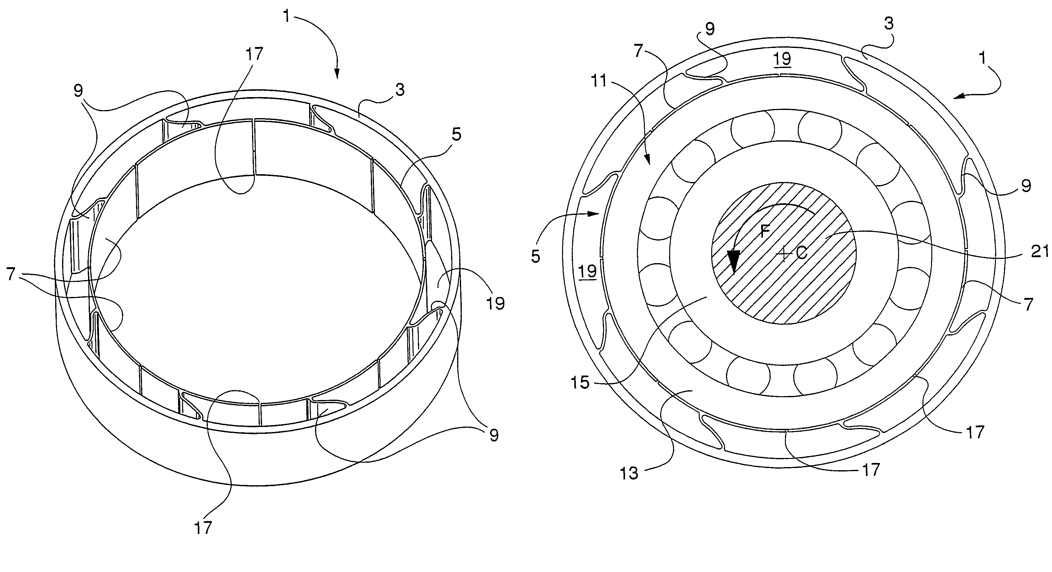
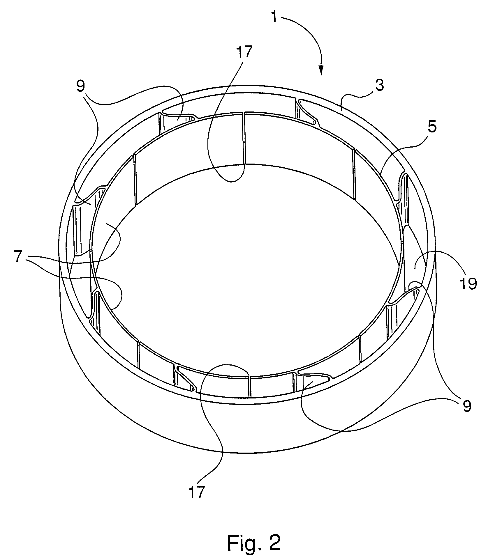
[0038]Referring to FIG. 2, there is shown a support ring 1 according to a preferred embodiment of the invention, comprising an outer cylindrical shell 3 and an inner cylindrical shell 5, connected together by a plurality of plates 9.

[0039]In this embodiment, inner shell 5 is broken by a plurality of slits 17 formed along corresponding generatrices, preferably equally spaced, so as to define a plurality of shoes 7, each connected to outer shell 3 by means of a corresponding plate 9.

[0040]Advantageously, the plates 9 are resilient, so that they allow a resilient radial displacement of shoes 7 and, consequently, prevent vibrations from radially propagating from the inside towards the outside through support 1.

[0041]Moreover the plates 9 are preferably obliquely arranged relative to the shells 3, 5, on planes parallel to the generatrices of these shells, and are formed with a curved shape, substantially an “S” shape.

[0042]In the embodiment shown in FIG. 2, support1 has been made with a ...


PUM


Abstract

A support ring (1) for rolling bearings (11), especially for rolling bearings applied to rotors with very high rotation speed, such as rotors of rotary vacuum pumps, the ring comprising a pair of concentric cylindrical shells (3, 5) connected together by a plurality of oblique radial plates (9), at least one of said shells (3, 5) being circumferentially broken so as to define a plurality of shoes (7), each shoe being connected to at least one of the radial plates (9) in such a manner as to define shoe portions or arcs (A1, A2) of different length, wherein the plates (9) are resilient and allow for the radial displacement of the shoes (7) so as to restrain vibrations of the rotating portion.

Description

BACKGROUND OF THE INVENTION[0001]The present invention relates to an annular support for rolling bearings.[0002]As known, rolling bearings are mechanical devices in which a relative motion, for instance between a rotating member and a stationary member (or between a pair of members rotating at different speeds), takes places with the interposition of balls or rollers rolling between two tracks, one of which is directly formed on the rotating member or a ring integral therewith, and the other is formed on the stationary member or a second ring integral therewith. The balls or rollers are generally spaced by a variously shaped cage, capable of separating and holding the balls or rollers.[0003]In some industrial applications, a resilient support is to be interposed between the bearings and the seat housing them, or between the bearings and the rotating member, e.g. a shaft. The resilient support is to compensate an alignment error, if any, of the same bearings and to prevent vibrations...

Claims


Application Information

Patent Timeline
Patent Type & Authority Patents(United States)
IPC IPC(8): F03B11/06
CPCF01D25/164F04D29/059F04D29/668F16C27/04F04D19/04F16C2360/45
Inventor CASARO, FAUSTO
Owner VARIAN SPA
Why Eureka
Try Eureka