Flanged graft for end-to-side anastomosis

a vascular graft and end-to-side technology, applied in the field of vascular grafts, can solve problems such as sub-intimal hyperplasia

Inactive Publication Date: 2009-06-30
BARD PERIPHERAL VASCULAR
View PDF81 Cites 11 Cited by
  • Summary
  • Abstract
  • Description
  • Claims
  • Application Information

AI Technical Summary

Problems solved by technology

In femoro-distal bypass grafting, there is growing evidence that compliance mismatch between the graft and the recipient artery

Method used


Image

  • Flanged graft for end-to-side anastomosis
  • Flanged graft for end-to-side anastomosis
  • Flanged graft for end-to-side anastomosis

Examples


Embodiment Construction

[0031]The following detailed description should be read with reference to the drawings, in which like elements in different drawings are identically numbered. The drawings, which are not necessarily to scale, depict selected preferred embodiments and are not intended to limit the scope of the invention. The detailed description illustrates by way of example, not by way of limitation, the principles of the invention. This description will clearly enable one skilled in the art to make and use the invention, and describes several embodiments, adaptations, variations, alternatives and uses of the invention, including what is presently believed to be the best mode of carrying out the invention.

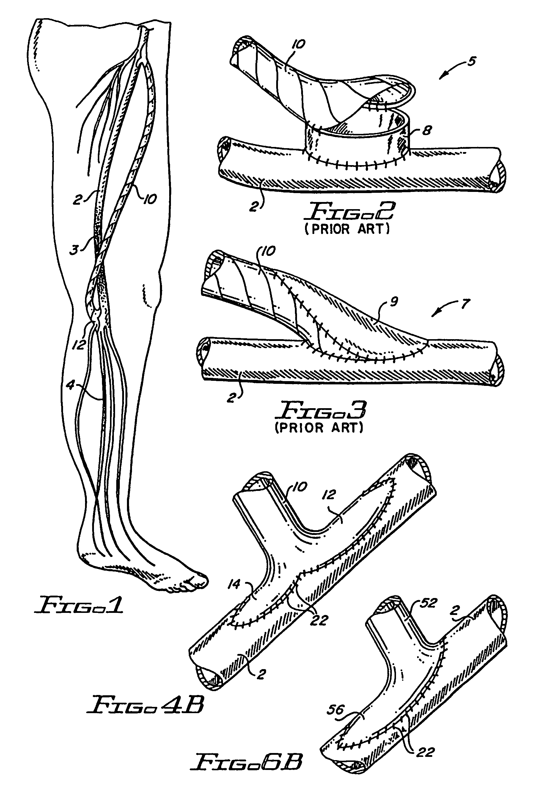
[0032]FIG. 1 illustrates a sequential femoro-posterior tibial bypass with a PTFE graft to an isolate popliteal segment and a distal graft. The use of a PTFE graft 10 bypassing an occluded section 3 of the femoral artery or an occluded section 4 of the popliteal artery to restore distal circulation ...


PUM


Abstract

An inventive flanged graft for end-to-side anastomosis includes a tubular graft member and a flanged section The type and size of the flanged section is determined by various factors such as identity of the receiving artery, position of the arteriotomy on the receiving artery, and luminal diameter of the graft. The graft is preferably anastomosed to the receiving artery using continuous sutures to join the arteriotomy to the peripheral edges flanged section.

Description

CROSS-REFERENCE TO RELATED APPLICATIONS[0001]This application is a continuation of application Ser. No. 09 / 898,793, filed Jul. 3, 2001, now U.S. Pat. No. 6,746,480 which is a continuation of application Ser. No. 09 / 125,907, filed Dec. 8, 1998, as a national stage application from International Application No. PCT / US96 / 02714, filed Feb. 28, 1996, now U.S. Pat. No. 6,273,912. This application expressly incorporates by reference the entirety of each of the above-mentioned applications as if fully set forth herein.STATEMENT REGARDING FEDERALLY SPONSORED RESEARCH OR DEVELOPMENT[0002]Not applicable.REFERENCE TO A COMPACT DISK APPENDIX[0003]Not applicable.FIELD OF THE INVENTION[0004]The present invention relates generally to vascular grafts, particularly to vascular grafts for end-to-side anastomosis for purposes of bypassing an occluded or diseased section of a blood vessel. More particularly, the present invention is a polytetrafluoroethylene graft having an integral terminal polytetrafl...

Claims


Application Information

Patent Timeline
IPC IPC(8): A61B17/08A61F2/06A61B17/11
CPCA61B17/11A61F2/06A61B2017/1135A61F2/064
Inventor SCHOLZ, HANSKRUGER, ULFSETTMACHER, UTZ
Owner BARD PERIPHERAL VASCULAR
Why Eureka
Try Eureka