
Endovascular stent insertion method

a stent and endovascular technology, applied in the field of endovascular stents, can solve the problems of anastomosis stricture, anastomosis stricture, and the experience surgeon cannot avoid a hundred, and achieve the effect of expanding the lumen and accurate sizing

Active Publication Date: 2012-01-17
VICTOR ACTION LTD
View PDF2 Cites 2 Cited by
  • Summary
  • Abstract
  • Description
  • Claims
  • Application Information

AI Technical Summary

Benefits of technology

"The invention provides a method for implanting an endovascular stent into a human body for end-to-end anastomosis. The method involves locating blood vessels to be connected, controlling blood flow, injecting a diluted medicine to expand the lumen and accurately size the vessels, selecting an endovascular stent with a waterproof inner membrane, disposing the stent in a transparent sheath, inserting a guide needle and guide wire into the blood vessels, sliding the stent into the blood vessels, and releasing the stent to fasten the blood vessels together. The invention has advantages such as reducing surgery time, eliminating the need for needle stitching, and being adaptable to anastomosis of artificial blood vessels or autogenous vessels. The diameter of the stent can be uniform or not equal between the front and rear sections. The T-shaped artificial blood vessel can effectively prevent thromboses from forming."

Problems solved by technology

However, either suture may lead to the problem of anastomosis stricture.
One is technical error.
Even an experienced surgeon can not avoid a hundred percent the possible adverse results of vascular anastomosis by sutures which may cause further anastomosis strictures.
Improvement of vascular anastomosis techniques had been an issue for vascular surgeons.
However, no perfect anastmosis technique had been developed yet.
Hence, it is limited to apply blood vessels with the same diameters.
Hence, the typical vascular anastomosis techniques using conventional sutures are disadvantageous.

Method used


Image

  • Endovascular stent insertion method
  • Endovascular stent insertion method
  • Endovascular stent insertion method

Examples


Embodiment Construction

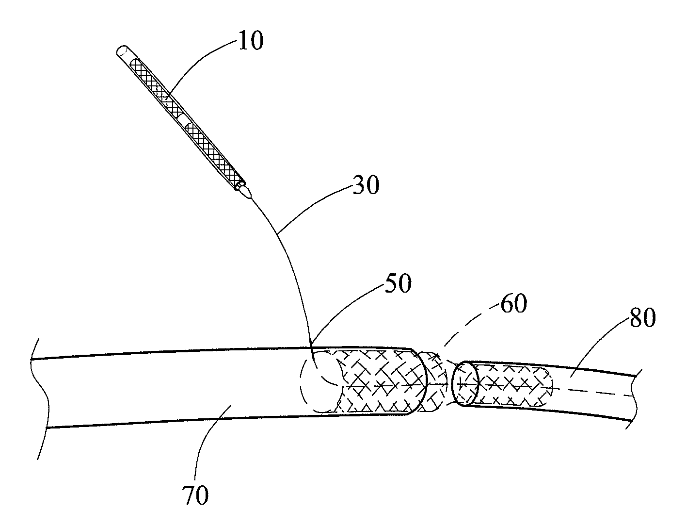
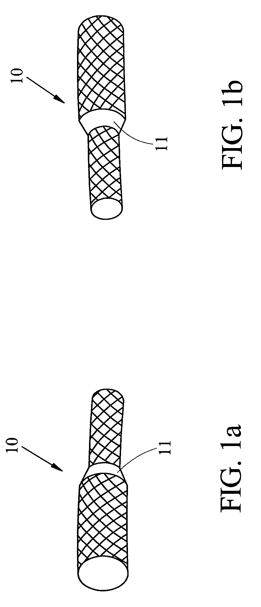
[0028]Referring to FIGS. 1a and 1b, an endovascular stent 10 according to the invention is shown. The endovascular stent 10 is self-expandable. A medical employee may pull a sheath and the endovascular stent 10 may slide to separate from the sheath subsequently. The separated endovascular stent 10 may expand immediately to have both ends securely fastened at one end of a first blood vessel and a facing end of a second blood vessel respectively. As a result, the two blood vessels are connected together.

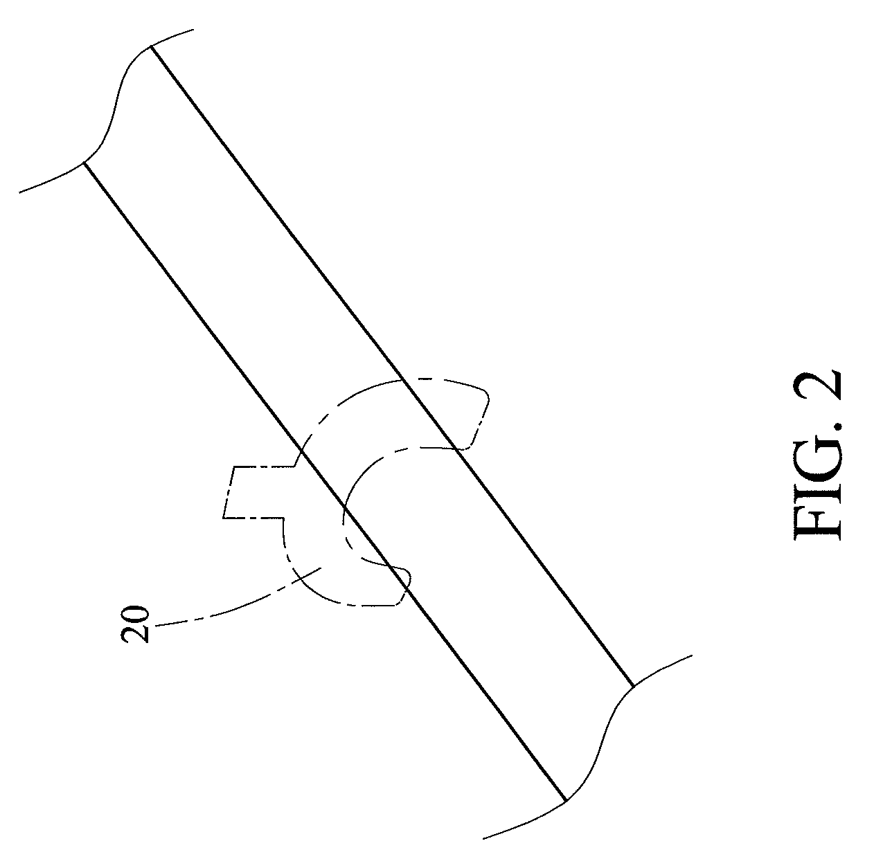
[0029]Referring to FIGS. 1a, 1b, 2 and 3, an endovascular stent insertion method with respect to end-to-end anastomosis in accordance with the invention is illustrated. The method comprises the following steps:

[0030]A1) locating two blood vessels to be anastomosed (i.e., connected together as target vessels);

[0031]B1) performing a blood control of a first blood vessel 70 and a blood control of a second blood vessel 80 respectively;

[0032]C1) Inserting a guide needle into each of the fir...


PUM


Abstract

Endovascular stent insertion methods are provided. In one embodiment for end-to-side anastomosis the method includes disposing an endovascular stent in a transparent sheath; inserting a guide wire through a guide needle into first and second blood vessels; sliding the endovascular stent into both the first and second blood vessels along the guide wire and the guide needle to dispose in a position between spaced first and second blood vessels; and pulling the sheath when an intermediate annular marker band of the endovascular stent seen through the transparent sheath is substantially disposed between the first blood vessel and the second blood vessel to release the endovascular stent so that the endovascular stent is adapted to expand to securely hold the facing ends of the first and second blood vessel together.

Description

BACKGROUND OF THE INVENTION[0001]1. Field of Invention[0002]The invention relates to endovascular stents and more particularly to an improved endovascular stent insertion method to perform sutureless vessel anastomosis.[0003]2. Description of Related Art[0004]With respect to prior vascular anastomosis techniques, end-to-side anastomosis and end-to-end anastomosis are most used techniques. Suture may be either continuous suture or interrupted suture. However, either suture may lead to the problem of anastomosis stricture. There are two causes for this problem. One is technical error. The other is abnormal vascular intimal hyperplasia caused by iatrogenic endovascular injury after suture injuries. Even an experienced surgeon can not avoid a hundred percent the possible adverse results of vascular anastomosis by sutures which may cause further anastomosis strictures.[0005]Improvement of vascular anastomosis techniques had been an issue for vascular surgeons. Surgeons tried whatever the...

Claims


Application Information

Patent Timeline
Patent Type & Authority Patents(United States)
IPC IPC(8): A61B17/08A61F2/06
CPCA61B17/11A61F2/06A61F2/064A61F2/88A61F2/95A61B19/54A61B2017/1107A61B2017/1132A61B2019/461A61F2/954A61F2002/065A61F2250/0039A61B90/39A61B2090/061
Inventor WU, MAO-TSUNYANG, CHENHUNG, YEN-NICHOU, CHIN-CHUAN
Owner VICTOR ACTION LTD
Learn More