Heat-dissipating device for motor base

a technology of heat dissipation device and motor base, which is applied in the direction of piston pumps, magnetic circuit rotating parts, magnetic circuit shapes/forms/construction, etc., can solve the problems of adverse effect of motor operation efficiency, and achieve the effect of assisting in heat dissipation

Inactive Publication Date: 2009-06-30
SUNONWEALTH ELECTRIC MACHINE IND
View PDF8 Cites 3 Cited by
  • Summary
  • Abstract
  • Description
  • Claims
  • Application Information

AI Technical Summary

Benefits of technology

[0007]A motor in accordance with the present invention comprises a base having a fixing seat, an axial tube mounted to the fixing seat, a rotor mounted to the axial tube, and a circuit board mounted to the base and comprising a stator and at least one heat-generating component. The base includes at least one slot. At least one fixed plate is located adjacent to the at least one slot. The at least one fixed plate is at a different height from the base. The at least one fixed plate is smaller than the at least one slot. The at least one heat-generating component is fixed to the at least one fixed plate. The at least one fixed plate assists in dissipation of heat generated by the at least one heat-generating component.
[0008]The heat generated by the heat-generating component is transferred to the casing, and the rotor assists in rapid heat-dissipation for the casing, preventing heat accumulation of the heat-generating component and maintaining normal operation of the motor.
[0014]In a further example, the at least one slot extends through the wall, forming an air inlet in the wall. Thus, a portion of the air currents created by the rotor may enter the base via the air inlet, allowing rapid heat-dissipation of the heat-generating component.

Problems solved by technology

Overheated and / or burn-out power transistors may occur in the motor and the operational efficiency of the motor is adversely affected, as no auxiliary heat-dissipation device is provided.

Method used


Image

  • Heat-dissipating device for motor base
  • Heat-dissipating device for motor base
  • Heat-dissipating device for motor base

Examples


first embodiment

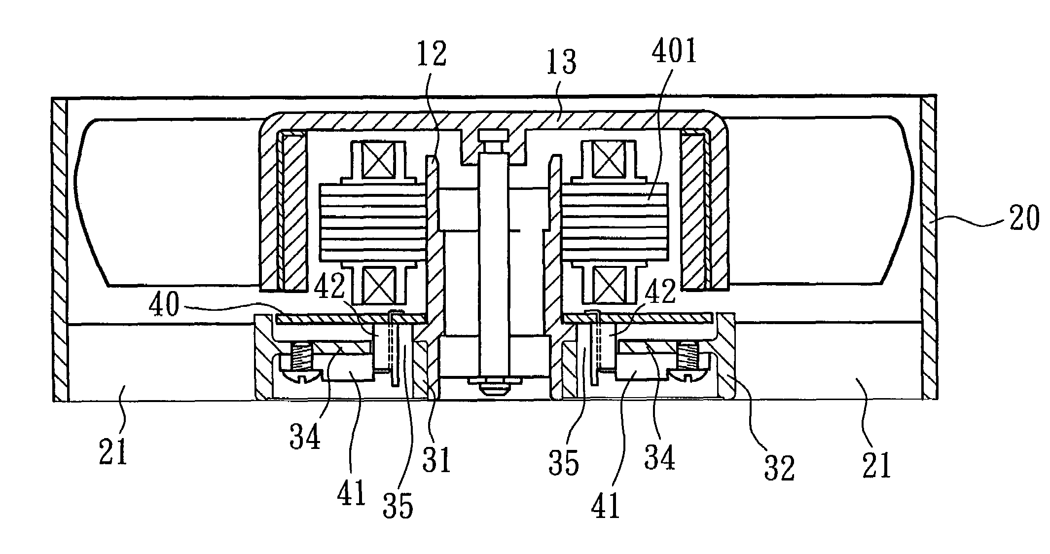
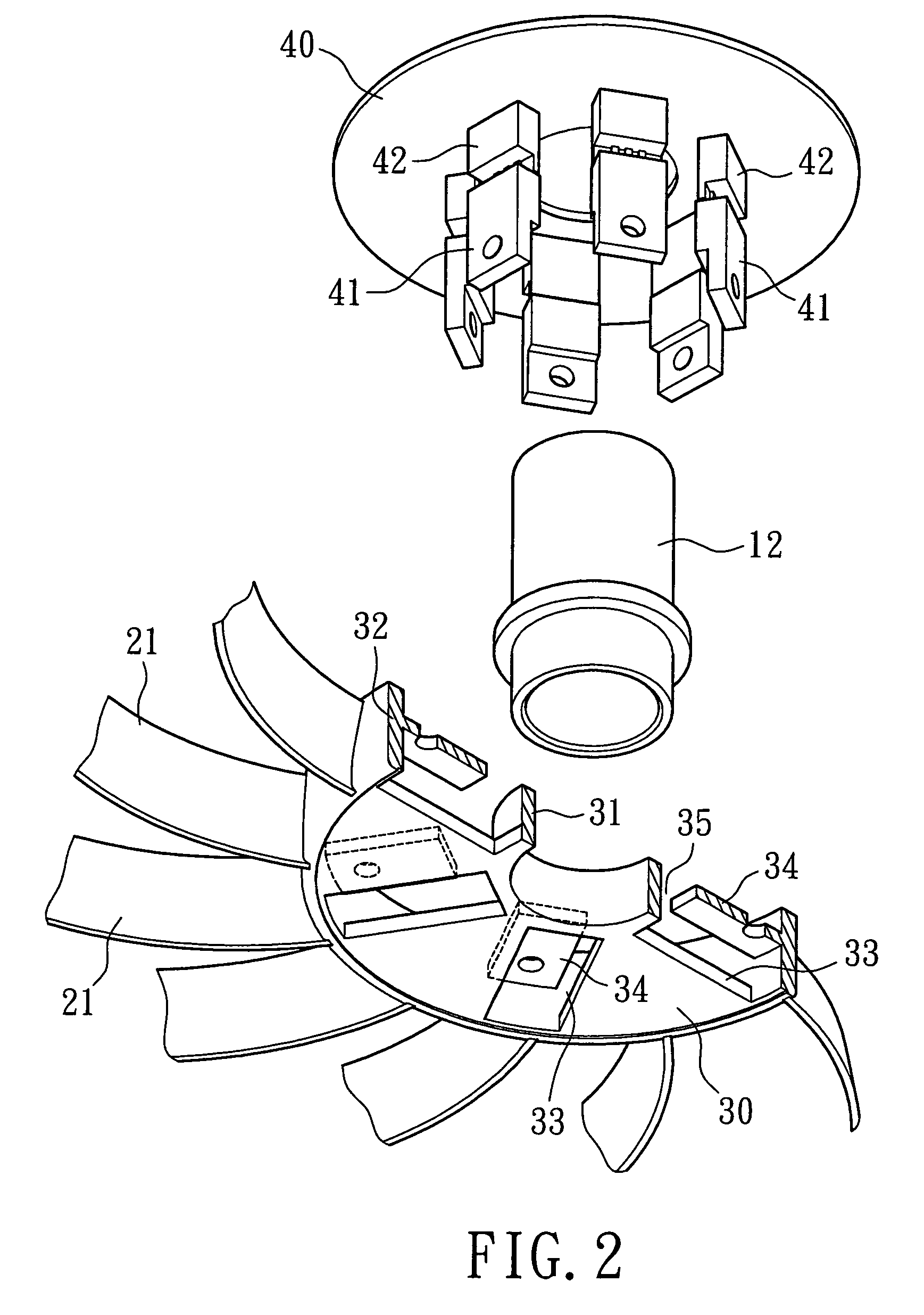
[0022]Referring to FIGS. 2 and 3, a motor in accordance with the present invention comprises a casing 20 and a rotor 13. The motor may be a high-power motor. The casing 20 includes a base 30. An axial tube 12 mounted to a fixing seat 31 located in a center of the base 30, and the rotor 13 is mounted to the axial tube 12. A wall 32 extends along an outer circumference of the base 30 and connected by a plurality of ribs 21 to an inner circumference of the casing 20. A circuit board 40 is mounted to the base 30. A stator 401 is mounted on the circuit board 40 and aligned with a magnet (not labeled) on the rotor 13.

[0023]At least one heat-generating component 41 is mounted on the circuit board 40. The heat-generating component 41 may be an IC control unit, a power transistor, etc. At least one positioning seat 42 is provided on a predetermined location of the circuit board 40, and the heat-generating component 41 is mounted on the positioning seat 42 and pin connection is carried out to...

second embodiment

[0027]FIG. 5 illustrates the invention, wherein at least one fixed plate 36 projects from an outer circumference of the fixing seat 31. The fixed plate 36 is at a different height from the base 30 and is smaller than the slot 33, providing a space 35 through which the heat-generating component 41 and the positioning seat 42 extend.

[0028]Similar to the first embodiment, the heat generated by the heat-generating component 41 is transferred to the casing 20, and the rotor 13 assists in rapid heat-dissipation for the casing 20, preventing heat accumulation of the heat-generating component 41 and maintaining normal operation of the high-power motor.

third embodiment

[0029]FIG. 6 illustrates the invention. A sticker or label bearing a trademark, model number, specification, etc of the motor is generally attached to a bottom side of the base 30 and thus seals the slot 33. In this embodiment, the slot 33 in the base 30 extends through the wall 32 to a position adjoining the fixed plate 34, forming an air inlet 37 in the wall 32. The air inlet 37 is not sealed by the label. Thus, a portion of the air currents created by the rotor 13 may enter the base 30 via the air inlet 37, allowing rapid heat-dissipation of the heat-generating component 41.


PUM


Abstract

A motor includes a base having a fixing seat, an axial tube mounted to the fixing seat, a rotor mounted to the axial tube, and a circuit board mounted to the base and including a stator and at least one heat-generating component. The base includes at least one slot. At least one fixed plate is located adjacent to the slot. The fixed plate is at a different height from the base. The fixed plate is smaller than the slot. The heat-generating component is fixed to the fixed plate. The fixed plate assists in dissipation of heat generated by the heat-generating component.

Description

BACKGROUND OF THE INVENTION[0001]1. Field of the Invention[0002]The present invention relates to a heat-dissipating device for a motor base. More particularly, the present invention relates to a heat-dissipating device for assisting in rapid heat dissipating for heat-generating components such as IC control units, power transistors, etc of a high-power motor, thereby maintaining optimal operational efficiency of the high-power motor.[0003]2. Description of Related Art[0004]FIG. 1 shows a motor with a conventional heat-dissipating device for a base of the motor. The motor comprises a casing 10 having a base 11, an axial tube 12 mounted to a center of the base 11, and a rotor 13 mounted to the axial tube 12. A wall 14 extends upwardly along an outer circumference of the base 11 and connected by a plurality of ribs 15 to an inner circumference of the casing 10. A circuit board 16 is mounted on top of the base 11. A stator 18 is mounted on the circuit board 16 and aligned with a magnet ...

Claims


Application Information

Patent Timeline
Patent Type & Authority Patents(United States)
IPC IPC(8): F04B35/04
CPCF04D25/0613F04D29/584F04D29/5813
Inventor HORNG, ALEXYIN, TSO-KUO
Owner SUNONWEALTH ELECTRIC MACHINE IND
Why Eureka
Try Eureka