Linear regulator with discharging gate driver

a technology of gate driver and linear regulator, which is applied in the direction of pulse generator, pulse technique, instruments, etc., can solve the problems of operation failure and increased electric power consumption, and achieve the effects of preventing operation failure, low electric power consumption, and preventing electric power consumption

Active Publication Date: 2009-06-30
SOCIONEXT INC
View PDF35 Cites 46 Cited by
  • Summary
  • Abstract
  • Description
  • Claims
  • Application Information

AI Technical Summary

Benefits of technology

[0018]The present invention has been proposed in view of the above problems. An object of the present invention is accordingly to provide a step-down circuit, which is, even when the output transistor is injected with electric charge due to an external causes such as, for example, noise from the outside, capable of preventing the step-down voltage from rising.
[0024]Consequently, by the step-down circuit of the present invention, the following advantage is provided. That is, even when the output transistor is injected with electric charge due to external causes such as, a noise from the outside, when the output voltage (step-down voltage) of the step-down circuit gets higher, since the output voltage is discharged. Thus, the step-down voltage (step-down output) is prevented from rising. As a result, the electric power consumption can be prevented from increasing resulting in low electric power consumption. Further, a voltage exceeding the voltage in which the load circuit operates normally can be prevented from being supplied. Thus, operation failure can be prevented resulting in a high reliability.

Problems solved by technology

Therefore, there arises such a problem that the electric power consumption is increased.
Furthermore, there arises another problem such that a voltage exceeding the voltage in which the load circuit operates normally is supplied resulting in an operation failure.
In this case also, the same problem as the above arises.

Method used


Image

  • Linear regulator with discharging gate driver
  • Linear regulator with discharging gate driver
  • Linear regulator with discharging gate driver

Examples


first embodiment

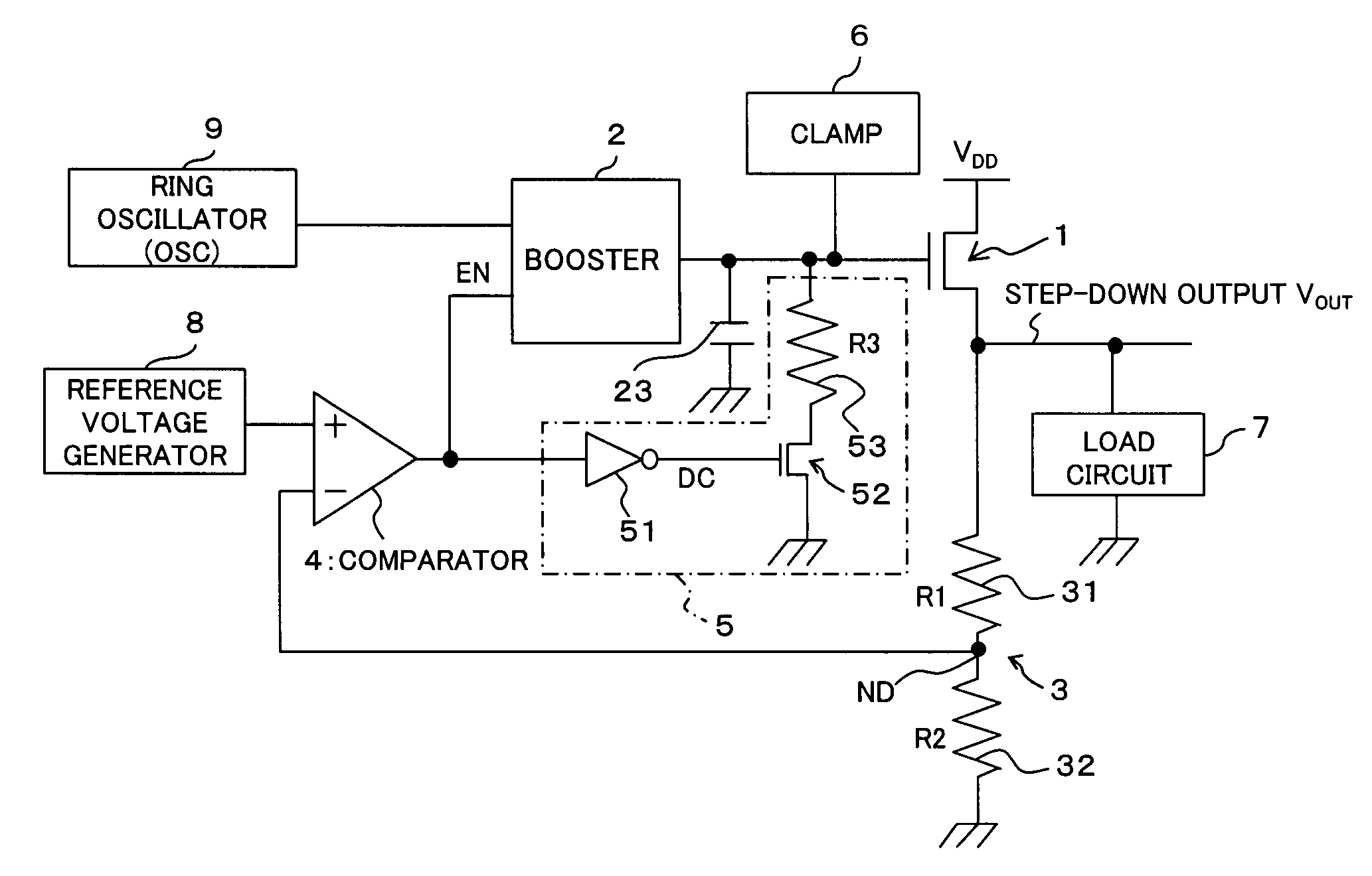
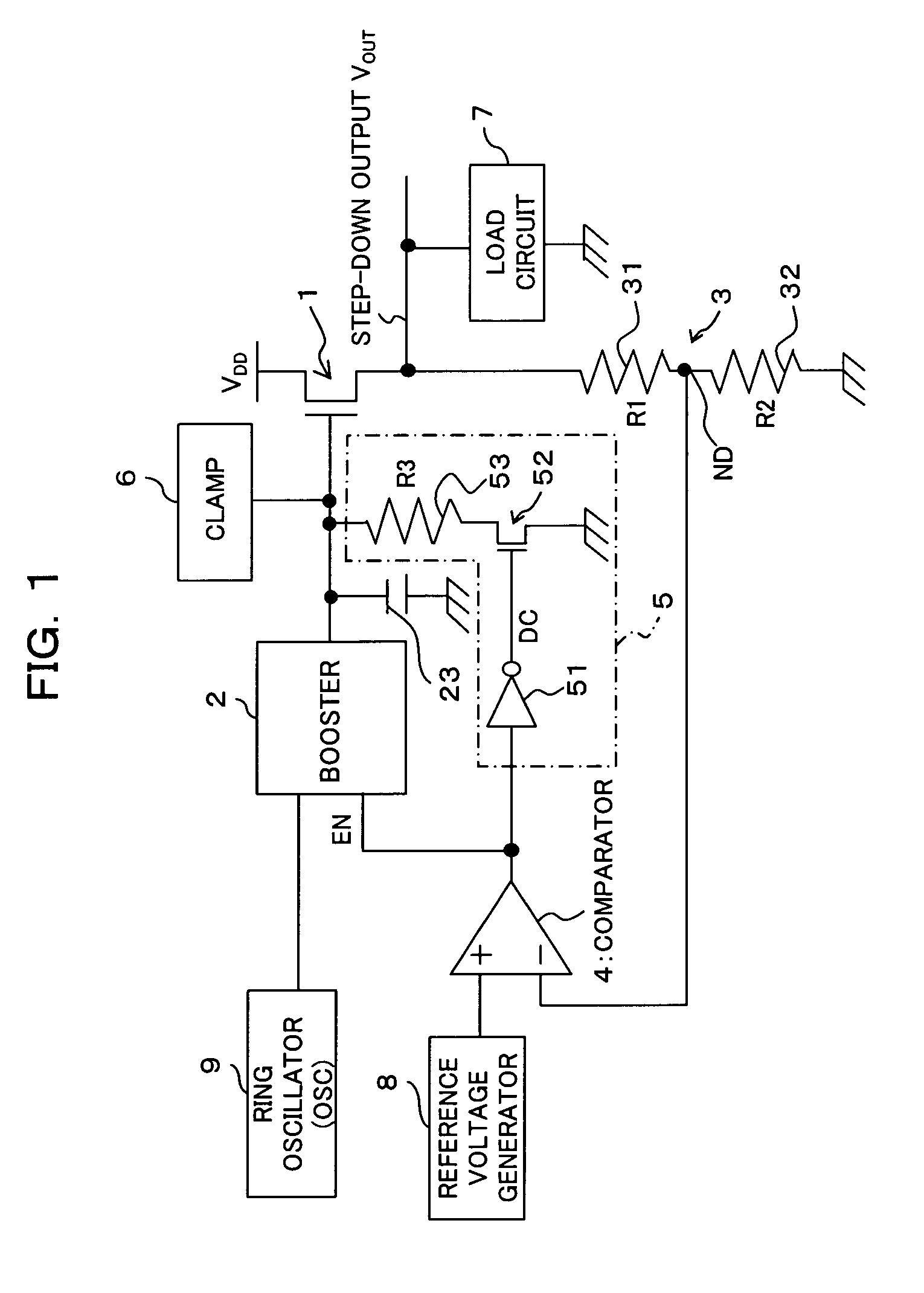
[0036]First of all, referring to FIG. 1 and FIG. 3, the configuration of a step-down circuit according to a first embodiment of the present invention will be described. The step-down circuit according to the embodiment is mounted on, for example, a semiconductor integrated circuit, which steps inputted power supply voltage down to a predetermined step-down voltage to output it to a load circuit. As shown in FIG. 1, the step-down circuit comprises an N channel type (Nch) transistor (output transistor; for example, nMOSFET) 1, a booster 2, a voltage dividing circuit 3 including two resistors 31 and 32 with resistance value R1 and R2 respectively, a comparator 4, a discharge circuit and a clamp circuit 6.

[0037]In this embodiment, taking the stability into consideration, as for the output transistors, not a P channel type transistor but an N channel type transistor is employed.

[0038]Here, a drain (input end) of the output transistor 1 is connected to the power supply line of the power s...

second embodiment

[0073]Next, the configuration of a step-down circuit according to a second embodiment of the present invention will be described with reference to FIG. 4 and FIG. 6.

[0074]Compared to the above-described first embodiment, the step-down circuit according to the second embodiment is different in the following points; i.e., the discharge transistor is a P channel type (Pch) transistor, and a level converter is connected to the gate of the P channel type transistor.

[0075]That is, the second embodiment is configured such that, as shown in FIG. 4, the N channel type transistor as the discharge transistor in the above-described first embodiment is replaced with a P channel type transistor (switching transistor; for example, pMOSFET) 60; and the inverter is replace with a level converter [H (High) level converter]61. In FIG. 4, the same elements as those in the above-described first embodiment will be given with the same reference numerals.

[0076]As described-above, the ON resistance of the N...

third embodiment

[0094]Next, referring to FIG. 7, the configuration of a step-down circuit according to a third embodiment of the present invention will be described.

[0095]Compared to the above-described second embodiment, the step-down circuit according to the third embodiment is different therefrom in the following point. That is, the EN signal, which controls the booster 2 to operate / stop, is fixed to “H” (H level; power supply voltage VDD) to allow the booster 2 to operate anytime. That is, in this embodiment, the input end of the booster 2 for inputting the EN signal is not connected to the output end of the comparator 4, but connected to the power supply line of the power supply voltage VDD so that the EN signal is at “H” (H level; power supply voltage VDD) anytime and the booster 2 is in operation anytime.

[0096]In this case, the booster 2 is allowed to operate anytime, and the step-down voltage (step-down output) VOUT, which is outputted from the output transistor 1, is controlled depending o...


PUM


Abstract

Even when, for example, electric charge is injected into the output transistor due to external factor such as a noise from the outside, to prevent the step-down voltage from rising, the step-down circuit is comprised of an N channel type output transistor which controls the voltage at the control end, a booster, which is connected to the control end of the output transistor and raises the voltage at the control end and a discharge circuit, which discharges the electric charge at the control end of the output transistor so that the power supply voltage inputted from the input end is stepped down to a desired step-down voltage and outputted from the output end.

Description

CROSS REFERENCE TO RELATED APPLICATIONS[0001]This application is based on and hereby claims priority to Japanese Application No. 2004-205912 filed on Jul. 13, 2004 in Japan, the contents of which are hereby incorporated by reference.BACKGROUND OF THE INVENTION[0002](1) Field of the Invention[0003]The present invention relates to a step-down circuit, which is mounted on, for example, semiconductor integrated circuits, for stepping down the power supply voltage.[0004](2) Description of Related Art[0005]Recently, minute processing for higher density integration of LSI (Large Scale Integration) has been progressing. As the higher integration progresses, the withstand voltage of transistor decreases; and thus, it is getting difficult to increase the power supply voltage.[0006]On the other hand, depending on the purpose, there is such a case that, due to the system power supply, the power supply voltage is high. In such a case, the power supply voltage cannot be used as it is for the oper...

Claims


Application Information

Patent Timeline
Patent Type & Authority Patents(United States)
IPC IPC(8): G05F1/56
CPCG05F1/575
Inventor NUNOKAWA, HIDEOKATO, TATSUOSUZUKI, MIKIMORISHITA, TOMONARI
Owner SOCIONEXT INC
Why Eureka
Try Eureka