
Circuit arrangement for providing a DC operating voltage

a technology of operating voltage and circuit arrangement, which is applied in the direction of emergency protective circuit arrangement for limiting excess voltage/current, emergency protective circuit arrangement, etc., can solve the problem of limiting the safe limitation threatening the circuit arrangement provided for connection to a mains voltage, and affecting the safety of the mains voltag

Inactive Publication Date: 2011-12-27
OSRAM GMBH
View PDF8 Cites 1 Cited by
  • Summary
  • Abstract
  • Description
  • Claims
  • Application Information

AI Technical Summary

Benefits of technology

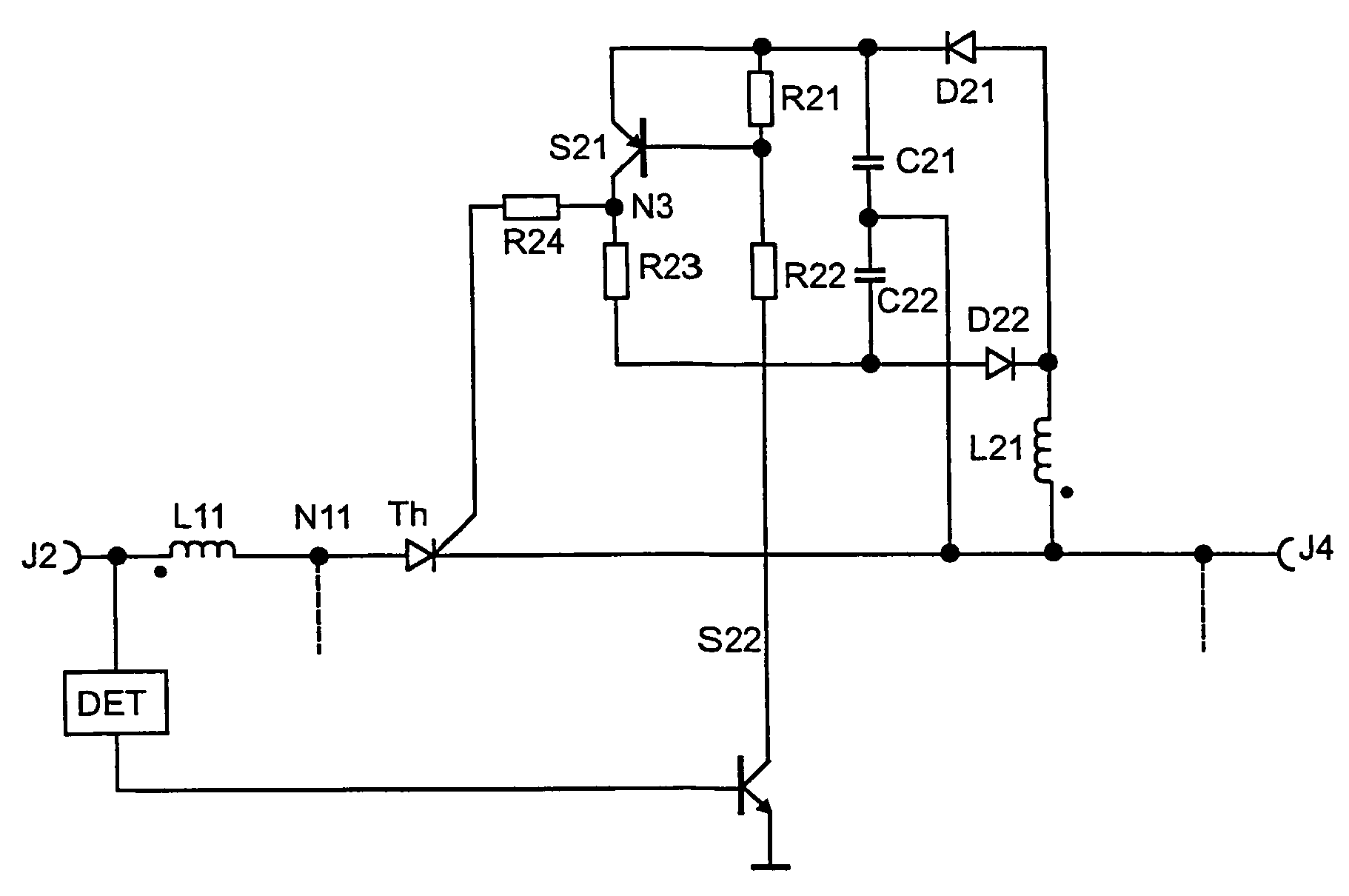
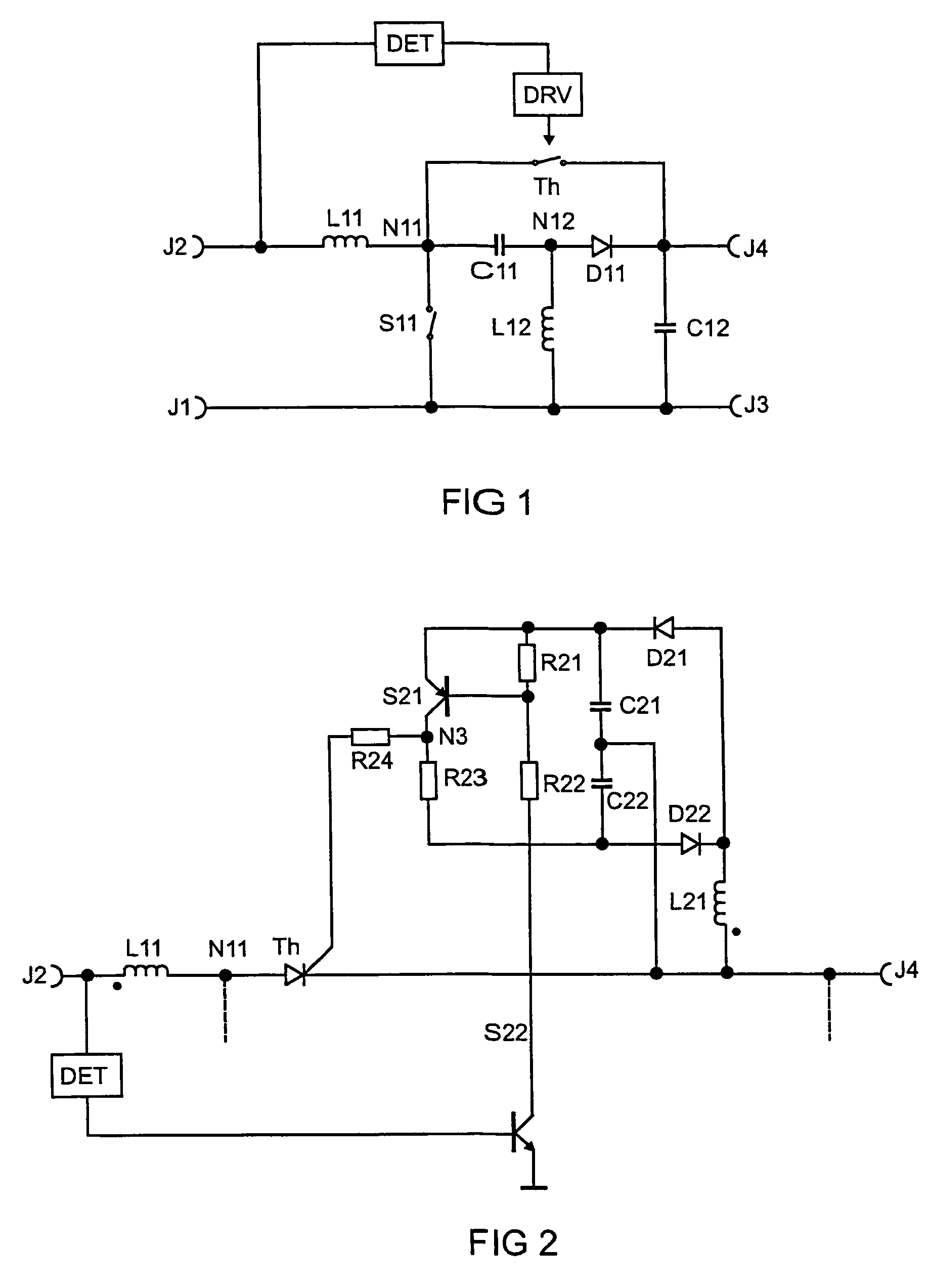
[0008]A circuit arrangement according to the invention comprises a dissipating switch, which, in the case of a mains overvoltage, connects the first working terminal of the switching transistor to the storage capacitor and, as a result, prevents a rise in the voltage at the switching transistor to destructive values.
[0011]A further aspect of the present invention relates to the implementation of the dissipating switch. Advantageously, it is implemented by a thyristor, which is triggered by a driver circuit, which prevents breakover triggering of the thyristor. This takes place by means of a negative voltage being applied to the gate of the thyristor as long as it is not intended to be triggered, the negative voltage being obtained from an auxiliary inductor, which is magnetically coupled to the storage inductor.

Problems solved by technology

Circuit arrangements which are provided for connection to a mains voltage are endangered by overvoltages which the mains voltage may have.
The disadvantage of these means is the safe limitation of the mains voltage in the case of severe faults in the mains voltage.
Often, operating circuits for lamps or other circuit arrangements for providing a DC voltage contain at least one switching transistor, whose dielectric strength is limited.
This results in large and expensive varistors or suppressor diodes.
However, this cannot be used in circuit topologies in which the storage capacitor is not directly coupled to the mains voltage.

Method used


Image

  • Circuit arrangement for providing a DC operating voltage
  • Circuit arrangement for providing a DC operating voltage

Examples


Embodiment Construction

[0004]The invention is based on the technical problem of providing a circuit arrangement which is protected against mains overvoltage without having the abovementioned disadvantages.

[0005]The invention is based on the knowledge that a storage capacitor can be used for limiting the voltage at a switching transistor by a dissipating switch connecting the switching transistor to the storage capacitor if there is a mains overvoltage.

[0006]In general, a circuit arrangement of the generic type has a rectifier, which makes available a rectified mains voltage at a first and a second mains terminal. Without limiting the universality, the first mains terminal is used as the reference potential. The rectified mains voltage feeds a clocked converter circuit, which usually makes available a DC operating voltage for operation of further circuit elements at a storage capacitor. The storage capacitor makes available the DC operating voltage with respect to the reference potential. The storage capac...


PUM


Abstract

The invention relates to a circuit arrangement for providing an operating DC voltage from a mains voltage, more particularly to operating circuits comprising a clocked electronic converter. Such operating circuits are preferably used for lamps or other light sources. The present invention protects such circuit arrangements from transient mains overvoltages. As soon as a mains overvoltage occurs a diverter switch Th connects the voltage-sensitive switch S11 of the electronic converter to a storage capacitor C12.

Description

TECHNICAL FIELD[0001]The present invention relates to circuit arrangements for providing a DC operating voltage from a mains voltage. In particular these circuits are operating circuits which contain a clocked electronic converter. Such operating circuits are preferably used for lamps or other light sources. The present invention is concerned with the protection of such circuit arrangements against mains overvoltage. Mains overvoltage is understood in the text which follows to mean a transient overvoltage which can result in destruction of the circuit arrangement. Values for the mains voltage which are permanently above a rated value are not taken into consideration.PRIOR ART[0002]Circuit arrangements which are provided for connection to a mains voltage are endangered by overvoltages which the mains voltage may have. Circuit arrangements which provide a DC operating voltage generally have a storage capacitor, at which the DC operating voltage for further circuit elements is present....

Claims


Application Information

Patent Timeline
Patent Type & Authority Patents(United States)
IPC IPC(8): H02H3/20
CPCH02M1/32H02M3/155H05B41/2853H02H9/005H02H7/125
Inventor STORM, ARWED
Owner OSRAM GMBH
Learn More