Message control protocol in a communications network having repeaters

a communication network and message control technology, applied in the field of communication, can solve the problems of inability to control the message control protocol of the communication network having the repeater, the inability to re-broadcast redundantly, and the inability to configure the wireless communication network. the effect of inefficiency

Active Publication Date: 2009-06-30
IOT LICENSING LLC
View PDF18 Cites 30 Cited by
  • Summary
  • Abstract
  • Description
  • Claims
  • Application Information

AI Technical Summary

Benefits of technology

[0013]In another embodiment of the present invention, a wireless communications system is provided, which includes a master apparatus, at least one remote device, and at least one repeater. The master apparatus includes a memory which is operable to store program and data information, a processor in communication with the memory which is operable to form and receive messages including a first message, with the messages being transmitted and received by a transceiver in communication with the processor. Each of the messages includes a control field and a plurality of information fields, the control field having a plurality of control bits including at least a first control bit indicative of whether data is contained in an information field and at least a second control bit indicative of a direction of transmission for the first message. The remote device(s) include a remote memory operable to store program information and data information, a remote processor in communication with the remote memory which is operable to form and receive messages, the messages transmitted and received by a remote transceiver in communication with the remote processor and operable to transmit and receive the messages. The repeater(s) include a repeater memory operable to store program information and data, a repeater processor in communication with the repeater memory which is operable to form and receive messages, the messages transmitted and received by a repeater transceiver in communication with the repeater processor and operable to transmit and receive messages, wherein the repeater processor is operable to determine if a message is to be re-transmitted based on information contained in the control field.
[0014]The control field may include a survey bit that indicates, when in a predetermined state (e.g., a binary 1 or a binary 0), one of the information fields includes information related to signal strength. The control field may also include a layer bit that indicates, when in a predetermined state, one of the information fields includes information related to a layer of the first message and a number of times the first message has been retransmitted. In accordance with embodiments of the present invention, the layer field of a message is changed by each repeater that retransmits the message. The control field may also include an address bit that indicates, when in a predetermined state, one of the information fields includes identification information of a remote device to which the first message is to be delivered. The control field may also include a trace bit that indicates, when in a

Problems solved by technology

However, such broadcast systems are inherently inefficient in that messages are re-broadcast redundantly in all directions and are received by other repeaters that are further away, as well as closer, to the master.
This redundancy, although inefficient, is required to ensure a high probability of successful communication of a message from a remote device to the master through the network.
However, limiting the number of times a message is repeated also limits the number of layers of repeaters that can be employed, thus limiting the range of the system.
This assignment of repeaters to layers, and to communicate with specified other repeaters, can become complex.
As will be understood, the conceptual free space communications network 100 of FIG. 1 is generally not possible to implement.
This is due to interference in the signals between a repeater and another repeater or a master

Method used


Image

  • Message control protocol in a communications network having repeaters
  • Message control protocol in a communications network having repeaters
  • Message control protocol in a communications network having repeaters

Examples


Embodiment Construction

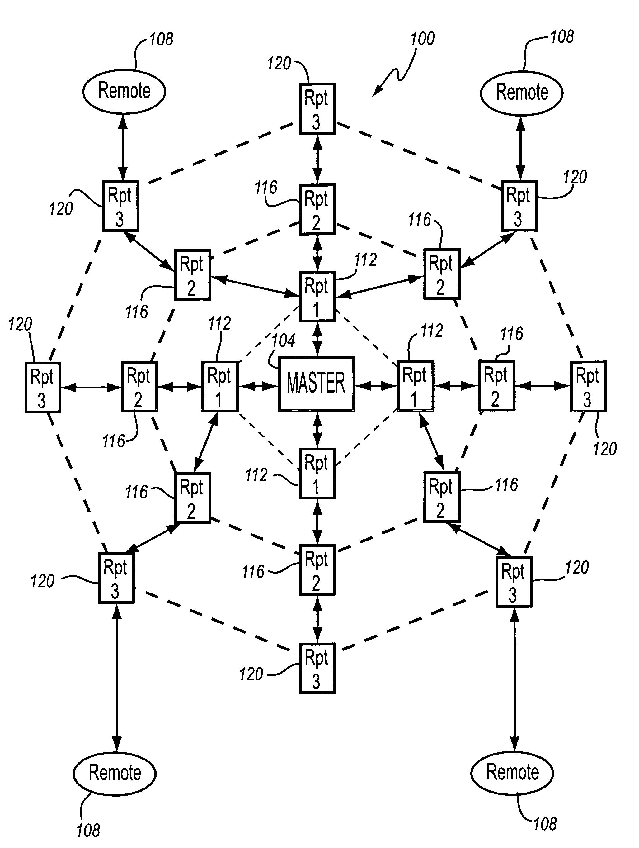
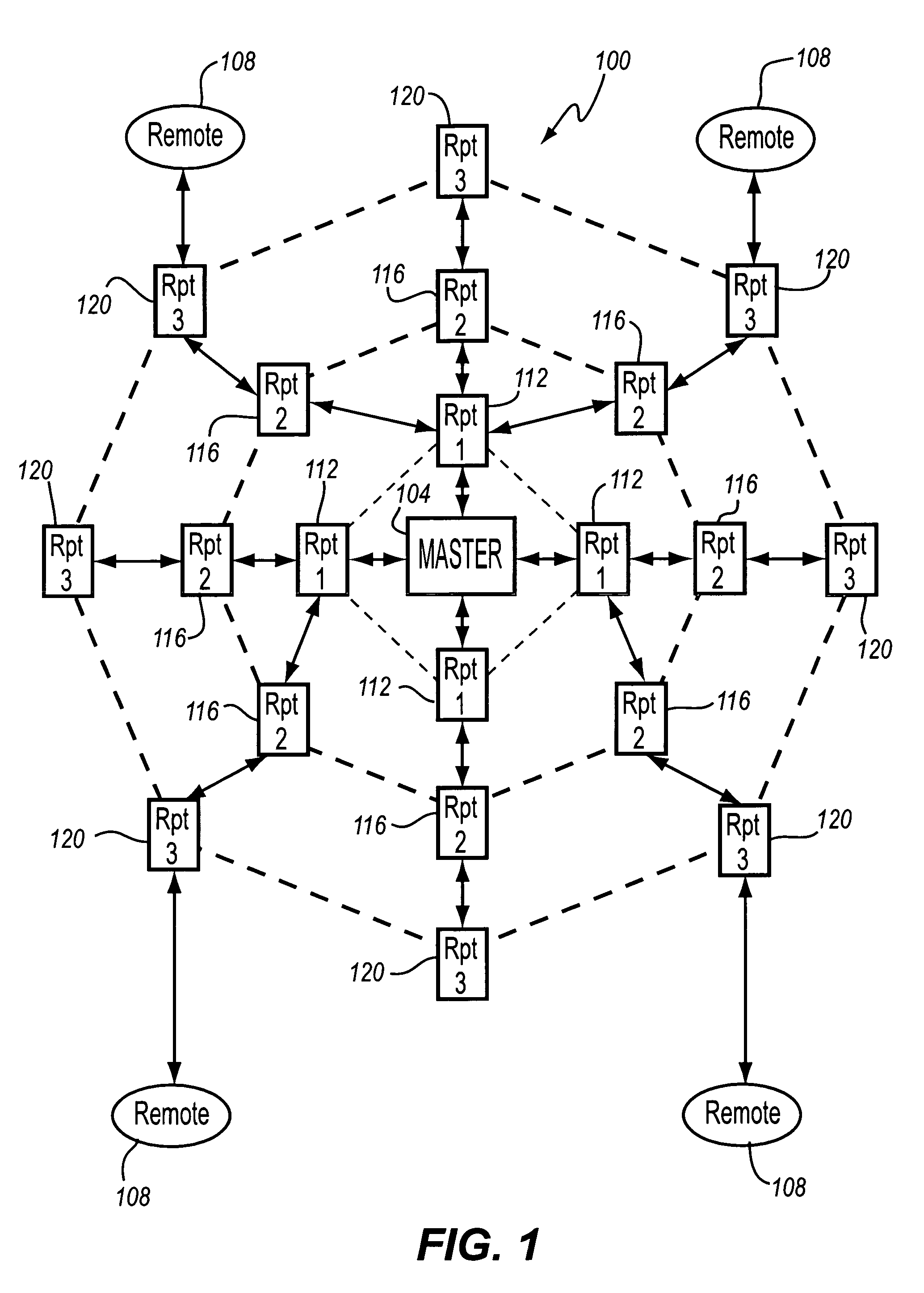
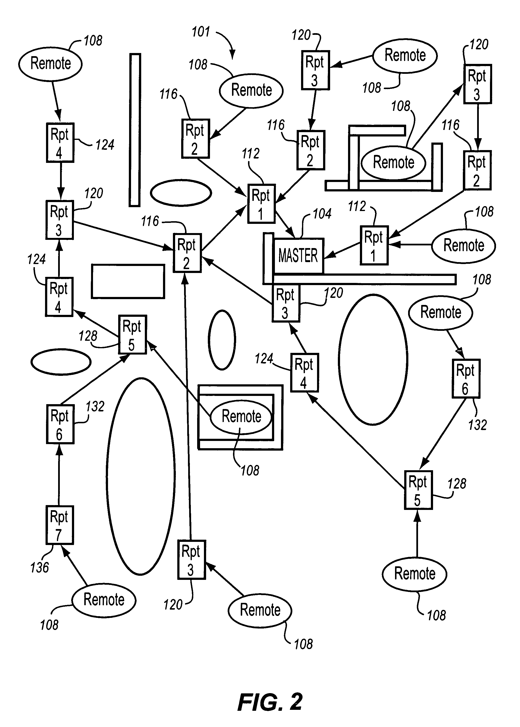
[0034]Referring now to FIG. 3, a block diagram illustration of a portion of a wireless communication network 200 of the present invention is described. In its simplest form, the wireless communication network 200 includes a master 204, a repeater 208, and a remote device 212. It will be understood that the wireless communication network 200 may contain a number of repeaters 208 and remote devices 212. Furthermore, multiple repeaters 208 may be required for the master 204 to communicate with a remote device 212, in a similar fashion as described above with respect to FIGS. 1 and 2. In such a case, the repeaters 208 are assigned layer numbers, and transmit messages to repeaters 208 having a lower layer number, for inbound messages to the master 204, or to repeaters 208 having a higher layer number, for outbound messages away from the master 204.

[0035]The master 204 includes a processor 216, a memory 220, and a transceiver 224. The processor 216 controls communication to and from the m...


PUM


Abstract

A wireless communications network which provides directed transmissions between components of the network is provided. The components within the wireless communications include a master apparatus, a plurality of remote devices, and a plurality of repeaters. The components within the wireless communications network communicate using messages which have a control field and at least one information field. Information within the control field is used by components to make determinations for retransmitting the message, or transmitting a predefined response to the message, such as a signal strength response. The components within the network use the messages to make a determination of a communications target, which may be used as a primary contact for transmitting information, automatically, and may repeat the determination at predetermined intervals. Thus, the wireless communications network is able to adapt over time to additional components added into the network, or changing environmental conditions in and around the network.

Description

CROSS REFERENCE TO RELATED APPLICATIONS[0001]This patent is a continuation-in-part of U.S. patent application Ser. No. 10 / 105,058, filed Mar. 21, 2002 now U.S. Pat. No. 7,154,866, entitled “Message Control Protocol in a Communications Network Having Repeaters,” the disclosure of which is hereby incorporated by reference herein in its entirety.FIELD OF THE INVENTION[0002]The present invention is directed generally to communications over a wireless communications network, and specifically to a message control protocol for a communications network having repeaters.BACKGROUND OF THE INVENTION[0003]A local on-site wireless monitoring network consists of remote monitoring devices, a central master device for controlling and collecting information from the remote devices, and distributed repeating devices (repeaters). The repeaters provide the means of expanding the communication coverage of the monitoring system by relaying messages to and from the remote devices and the master. Such a mo...

Claims


Application Information

Patent Timeline
IPC IPC(8): H04B7/14
CPCH04B7/155H04L1/1867H04L45/26H04W88/04H04B7/15521H04L2001/0097H04W8/26H04W24/00H04W28/04H04W40/08H04W48/08H04W52/0219H04W52/0245Y02D30/70
Inventor SHURMANTINE, NEALBURKHARD, DARYLDUNBAR, STEVEN T.HUME, DONALD J.KOONCE, NATHANKOONCE, STEVEPIERCE, PRESTON
Owner IOT LICENSING LLC
Why Eureka
Try Eureka