Physical quantity sensor

a sensor and physical quantity technology, applied in the field of sensors, can solve the problems of affecting the whole of the sensor device, the diaphragm section of the sensor, so as to reduce the influence of the mounting member on the sensor device, reduce the effect of the stress imposed, and improve the accuracy of measuremen

Active Publication Date: 2009-07-07
HITACHI ASTEMO LTD
View PDF13 Cites 8 Cited by
  • Summary
  • Abstract
  • Description
  • Claims
  • Application Information

AI Technical Summary

Benefits of technology

[0007]The thermal air flow sensor disclosed in JP,A 2001-021401 is intended to suppress flexion caused by unbalance among internal stresses generated in the diaphragm. The flexion caused by the internal stresses is therefore reduced, but stresses imposed from the exterior are not taken into consideration. Also, the stresses applied from the mount member to the sensor device affect the whole of the sensor device in addition to the diaphragm section. Accordingly, those stresses affect not only the resistor used for detecting the physical quantity, but also a wiring section for taking out the electric signal. In other words, the influence of stresses generated from the member for mounting the sensor device is not yet overcome.
[0008]An object of the present invention is to provide a physical quantity sensor which can reduce resistance changes due to stresses imposed on a sensor device and can ensure highly accurate measurement.
[0015]Further, when the resistor is formed on a semiconductor substrate, variations of resistance values can be reduced by forming the resistor including Rl and Rt so as to have a substantially constant line width. The resistance value ratio of Rl to Rt can be simply adjusted by a method of changing respective lengths or widths of the resistance components Rt and Rl. However, the resistance value ratio of Rl to Rt is preferably adjusted by changing the resistance lengths while the resistance widths are kept the same. The reason is as follows. To suppress a reduction in sensitivity of the wiring resistance, the resistance value of a detection section of the sensor is required to be increased and the line width of the resistor is narrowed correspondingly. When the resistor having a thinner pattern is etched, the influence of variations (overetching) in etching amount becomes larger. By forming the resistor so as to have a substantially constant line width, the resistance ratio of Rl to Rt can be kept the same in spite of overetching, whereby high accuracy is ensured.
[0017]Therefore, a drive circuit can be constituted such that even when the wiring resistance on the power supply side and the wiring resistance on the ground side of the resistor are changed due to stress distortions, etc., the changes caused by distortions of the wiring resistances of the resistor can be ignored. As a result, the influence generated by stresses imposed on a wiring section of the sensor can be reduced.
[0018]According to the present invention, the physical quantity sensor is provided which can reduce effects of stresses imposed on the sensor device and ensure highly accurate measurement.

Problems solved by technology

The larger resistance change becomes a factor deterioraing the measurement accuracy.
Also, the stresses applied from the mount member to the sensor device affect the whole of the sensor device in addition to the diaphragm section.
In other words, the influence of stresses generated from the member for mounting the sensor device is not yet overcome.

Method used


Image

  • Physical quantity sensor
  • Physical quantity sensor
  • Physical quantity sensor

Examples


first embodiment

[0034]The first embodiment represents, as one example of the physical quantity sensor, a thermal air flow sensor for measuring the flow rate of intake air in an internal combustion engine of an automobile, etc.

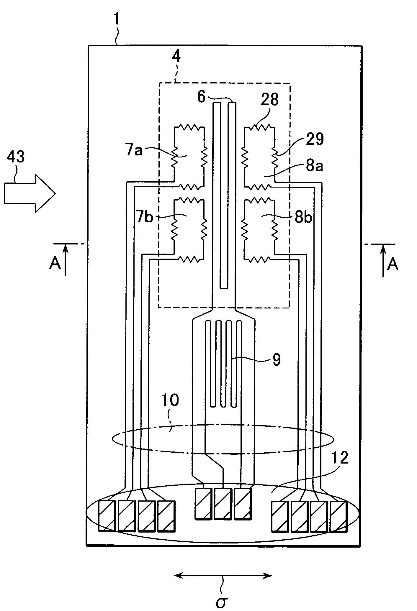
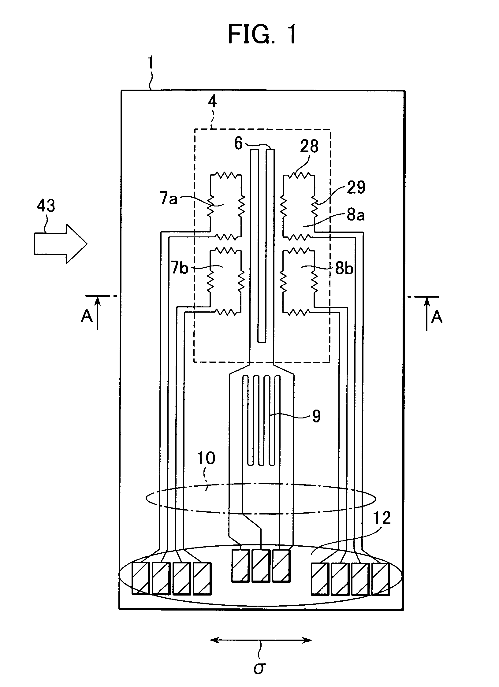
[0035]FIG. 1 is a schematic plan view of a sensor device of the thermal air flow sensor according to the first embodiment, and FIG. 2 is a sectional view taken along the line A-A in FIG. 1. As shown in these drawings, a sensor device 1 is formed on a semiconductor substrate (base) 2 made of a single-crystalline silicon (Si) wafer as follows.

[0036]A cavity 3 is formed in a part of the semiconductor substrate 2 by anisotropic etching. The cavity 3 is in the form of a rectangular hole as viewed in a plan. A diaphragm 4 is formed at one side of the cavity 3. The diaphragm 4 is made of an electric insulating film 5 of silicon dioxide (SiO2) that is formed on one surface of the semiconductor substrate 2 by thermal oxidation or CVD (Chemical Vapor Deposition).

[0037]A heating resistor...

second embodiment

[0058]A second embodiment will be described below with reference to FIG. 7. This embodiment also represents the case where the present invention is applied to the thermal air flow meter. Since the basic principle and structure are the same as those in the first embodiment, only different points are described here and a description of common points is omitted.

[0059]FIG. 7 is a plan view showing shapes of the temperature sensitive resistors 8a and 8b in this second embodiment. While in the first embodiment the temperature sensitive resistors 8a and 8b are arranged in separate areas divided in the vertical direction along the length of the heating resistor 6, the temperature sensitive resistors 8a and 8b in the second embodiment are arranged in such a way that the respective vertical resistance components and the respective horizontal resistance components of the temperature sensitive resistors 8a and 8b are extended in interdigitated (or interlaced) relation in parallel as shown. Furt...

third embodiment

[0065]A third embodiment will be described below. This embodiment represents the case where the present invention is applied to an acceleration sensor of the type employing a heating resistor, which can be used as an acceleration sensor and an inclination sensor in an automobile, etc.

[0066]One example of the known heating-resistor acceleration sensor is disclosed in U.S. Pat. No. 5,581,034.

[0067]FIG. 8 is a schematic plan view of a sensor device of a thermal acceleration sensor according to the second embodiment, and FIG. 9 is a sectional view taken along the line B-B in FIG. 8. Though not shown in these drawings, a sensor device 30 is mounted in an enclosed container which is filled with a fluid having a small thermal conductivity, such as air or xenon (Xe).

[0068]As shown in FIGS. 8 and 9, the sensor device 30 is entirely formed by using, as a base, a semiconductor substrate 31 made of a single-crystalline silicon (Si) wafer. A cavity 34 is formed in a part of the semiconductor sub...


PUM


Abstract

A highly accurate physical quantity sensor which can ensure reliability in strength and reduce resistance changes caused by stresses. Assuming, with respect to stress σ imposed on a substrate in a predetermined direction (e.g., direction in which maximum stress is imposed), a parallel direction to be a horizontal direction and a perpendicular direction to be a vertical direction, each of resistors of the sensor has a horizontal resistance component Rl and a vertical resistance component Rt. When a ratio of a piezoresistance coefficient πl of the horizontal resistance component Rl, which is provided when the stress imposed on the substrate is applied to the horizontal resistance component Rl, to a piezoresistance coefficient πt of the vertical resistance component Rt, which is provided when the stress is applied to the vertical resistance component Rt, is πl:πt=−n:1 (n:integer), a resistance value ratio of the vertical resistance component Rt to the horizontal resistance component Rl is set substantially equal to the ratio of the piezoresistance coefficient πl to πt.

Description

BACKGROUND OF THE INVENTION[0001]1. Field of the Invention[0002]The present invention relates to a sensor including a resistor formed on a substrate and detecting a predetermined physical quantity. More particularly, the present invention relates to a physical quantity sensor which is applied to, for example, a flow sensor for detecting the flow rate of a fluid, an acceleration sensor, and an inclination sensor.[0003]2. Description of the Related Art[0004]As a flow sensor for detecting an intake air amount in an internal combustion engine such as an automobile, it is proposed to manufacture a sensor device on a semiconductor substrate made of, e.g., silicon (Si) by using the micromachining technology. That type of flow sensor is advantageous in that it can be mass-produced at a low cost, has a small size, and can be driven with low electric power. That type of flow sensor is mainly practiced as an air flow sensor employing a heating resistor, which can directly measure a mass flow r...

Claims


Application Information

Patent Timeline
Patent Type & Authority Patents(United States)
IPC IPC(8): G01F1/68
CPCG01C9/00G01P15/008G01F1/69G01F1/6845
Inventor NAKANO, HIROSHIMATSUMOTO, MASAHIROYAMADA, MASAMICHINAKADA, KEIICHIWATANABE, IZUMI
Owner HITACHI ASTEMO LTD
Why Eureka
Try Eureka