Attachment for fuel injectors in direct injection fuel systems

a fuel system and fuel injector technology, applied in the direction of liquid fuel feeders, machines/engines, mechanical equipment, etc., can solve the problems of affecting the retention and orientation of the fuel injector within the fuel rail, certain degree of misalignment between the injector and the cup, and the applicability of the approach is not without disadvantages

Inactive Publication Date: 2009-07-07
MILLENNIUM INDS
View PDF27 Cites 55 Cited by
  • Summary
  • Abstract
  • Description
  • Claims
  • Application Information

AI Technical Summary

Benefits of technology

[0007]Further features and advantages of the present invention will become more apparent to those skilled in the art after a review of the invention as it is shown in the accompanying drawings and detailed description.

Problems solved by technology

A challenge to these systems resides in the retention of the fuel injectors in the cups of the fuel rail in view of the relatively high system pressure (i.e., on the order of 10-30 MPa (1450-4350 psi)) and the pressure created as a result of combustion events occurring in the combustion chamber of the engine.
These approaches, however, are not without their disadvantages.
As a result, when the cup, injector and clip are assembled, there is a certain degree of misalignment between the injector and the cup.
As a result, the load applied to the injector, clip, and / or rail primarily by the high pressure attendant in the system is overloaded to one side of the injector, thereby resulting in the application of a bending moment on the injector and / or clip, which can adversely impact the retention and orientation of the fuel injector within the cup of the fuel rail.

Method used


Image

  • Attachment for fuel injectors in direct injection fuel systems
  • Attachment for fuel injectors in direct injection fuel systems
  • Attachment for fuel injectors in direct injection fuel systems

Examples


Embodiment Construction

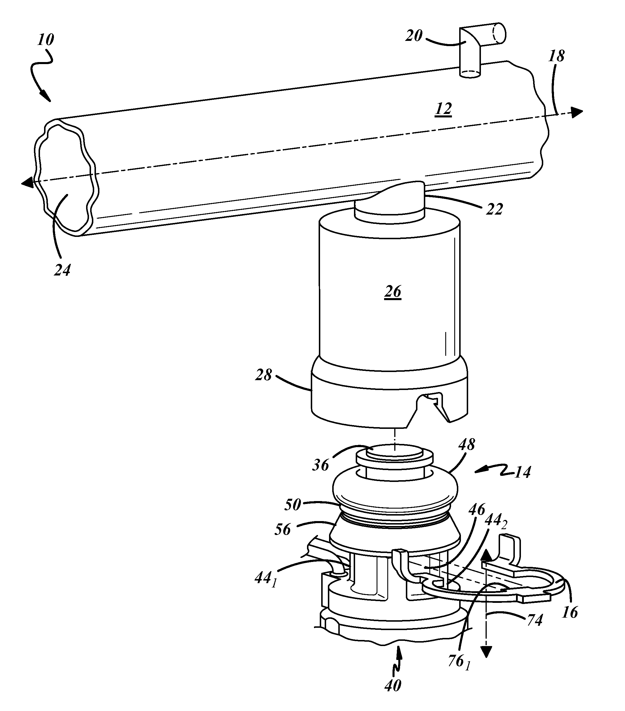
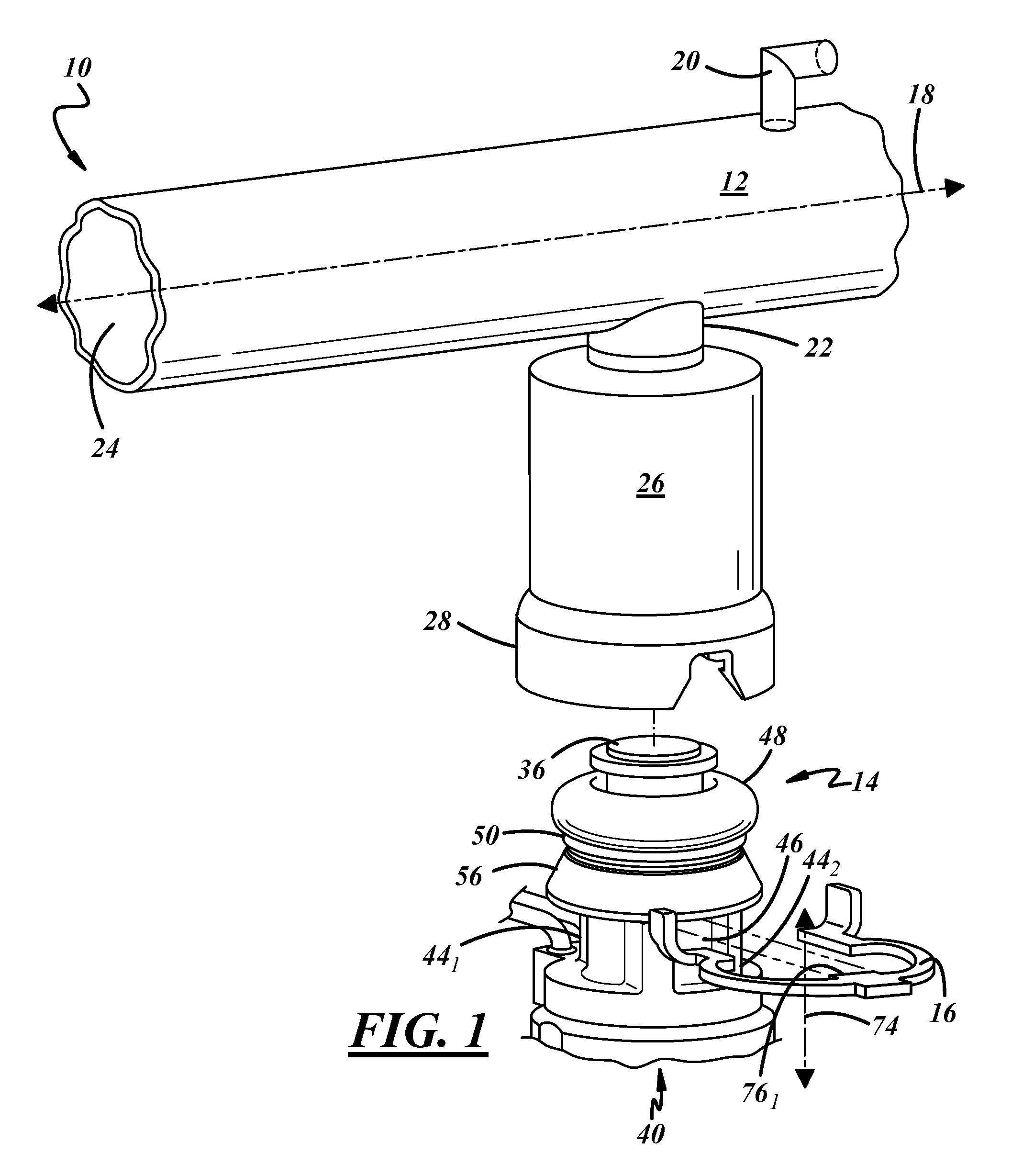
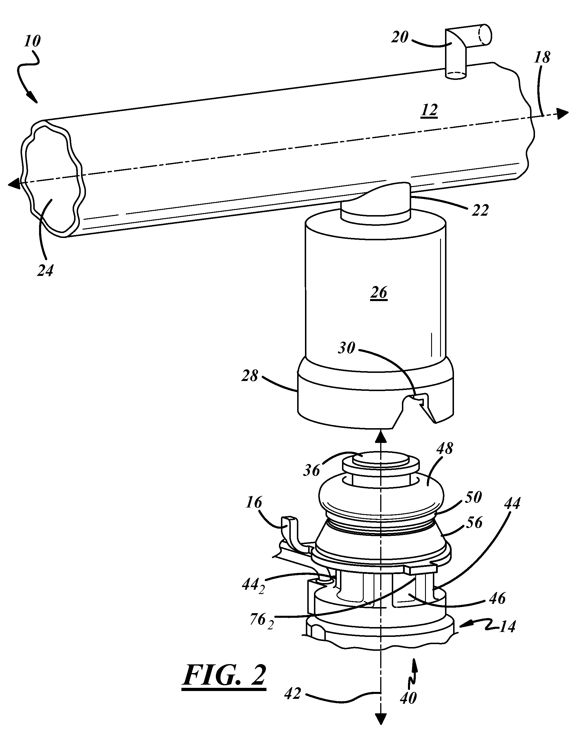
[0021]Referring now to the drawings wherein like reference numerals are used to identify identical components in the various views, FIGS. 1-3B illustrate one exemplary embodiment of a fuel delivery system 10 in various states of assembly. In an exemplary embodiment, fuel delivery system 10 includes a fuel rail 12, a fuel injector 14 and a retention clip 16.

[0022]With continued reference to FIGS. 1-3A, fuel rail 12 is a hollow-bodied fluid conduit that defines a longitudinal axis 18 extending from one end thereof to the other. Fuel rail 12 includes an inlet 20, at least one outlet 22, a fluid passageway 24 between said inlet 20 and outlet 22 and at least one receptor cup 26 associated with said outlet 22. Inlet 20 is configured to be coupled to a fuel source, such as, for example, the fuel tank of an automobile, to allow for the communication of fuel from the fuel source to fluid passageway 24 of fuel rail 12. Outlet 22 of fuel rail 12 is configured to allow communication of fuel fro...


PUM


Abstract

A fuel delivery system comprising a fuel rail having an outlet and a receptor cup associated therewith. The system further including a fuel injector having an inlet, an outlet and a body therebetween. The inlet is configured for insertion into the cup of the fuel rail and for fluid communication with the outlet thereof. The system still further including a retention clip configured for engagement with the fuel injector and the cup in order to couple the fuel injector with the fuel rail. In the inventive system, the fuel injector further includes a load distribution feature. This feature is configured to engage a portion of the retention clip and to assist with the distribution about the clip of a load applied to the injector.

Description

FIELD OF THE INVENTION[0001]The field of the present invention is fuel delivery systems. More particularly, the present invention relates to an arrangement for attaching one or more fuel injectors to a fuel rail in gasoline direct injection fuel delivery systems.BACKGROUND OF THE INVENTION[0002]Fuel delivery systems for direct injection applications, such as, for example, fuel-injected engines used in various types of on-road and off-road vehicles, typically include one or more fuel rails having a plurality of fuel injectors associated therewith. In such applications, the fuel rails may include a plurality of apertures or outlets in which injector sockets or cups are affixed. The fuel injectors are then inserted into the injector cups so as to allow for the fuel flowing in the fuel rail to be communicated to the fuel injectors. The fuel communicated from the fuel rail to the fuel injectors is then communicated to the combustion chamber of the engine associated with the fuel delivery...

Claims


Application Information

Patent Timeline
Patent Type & Authority Patents(United States)
IPC IPC(8): F02M61/14F02M61/18
CPCF02M55/004F02M55/025F02M55/02F02M55/005F02M2200/853
Inventor DOHERTY, ROBERTZDROIK, MICHAEL J.
Owner MILLENNIUM INDS
Why Eureka
Try Eureka