It is technically difficult to visualize the steam entering a cold formation with extremely highly
viscous oil, while a completely open wellbore is readily available for fluid flow away from the formation.
This situation is not only physically impossible but it thermodynamically impossible for the steam fluid to flow out of, and hot oil flow back into the same perforations simultaneously.
This type of downhole
flange connection is extremely difficult if not impossible to implement in current oilfield practice.
This technology while theoretically possible is operationally difficult to hit such a small underground target, i.e the axial cross-section of a typical 8-inch wellbore using a horizontal penetrating
drill bit.
Similar to U.S. Pat. No. 5,896,928 this
system is unable to operate based on the sensible characteristics of the flowing fluid as is needed in the case of steam, flow where pressure is a minor parameter in determining flow regimes.
The 20050072578 application does not address this fact and as such is incapable of discriminating between hot oil, hot water and steam in the flow
stream and will be inadequate as a controller of steam flow and a reliable steam shut off mechanism as is needed in heavy
oil field steam displacement processes.
This barrier slows down the recovery under the SAGD
system of dual
horizontal wells since the steam
bank formation is slowed by the shale.
This
system is similar to other approaches in the prior art and has a serious drawback in that neither investigator describes how the backwards flow from the “
toe” to the “
heel” can occur under reservoir conditions with the extremely viscous in-situ oil.
There is no viable mechanism for the hot oil to travel to the producing point at the
heel.
Very few of these prior art systems, except the SAGD and Huff & Puff processes, have been used in the industry with any success because of their technical complexity, operational difficulties, and being physically impossible to implement or being extremely uneconomical systems.
Secondly, the
large distance between the top of the formation and the bottom of the formation will cause condensation of the drive steam allowing essentially hot water to be produced at the bottom with low quality steam, both fluids being re-circulated back to the surface.
In addition, the mechanism to heat the near wellbore can only be based on conductive
heat transfer through the steel casing.
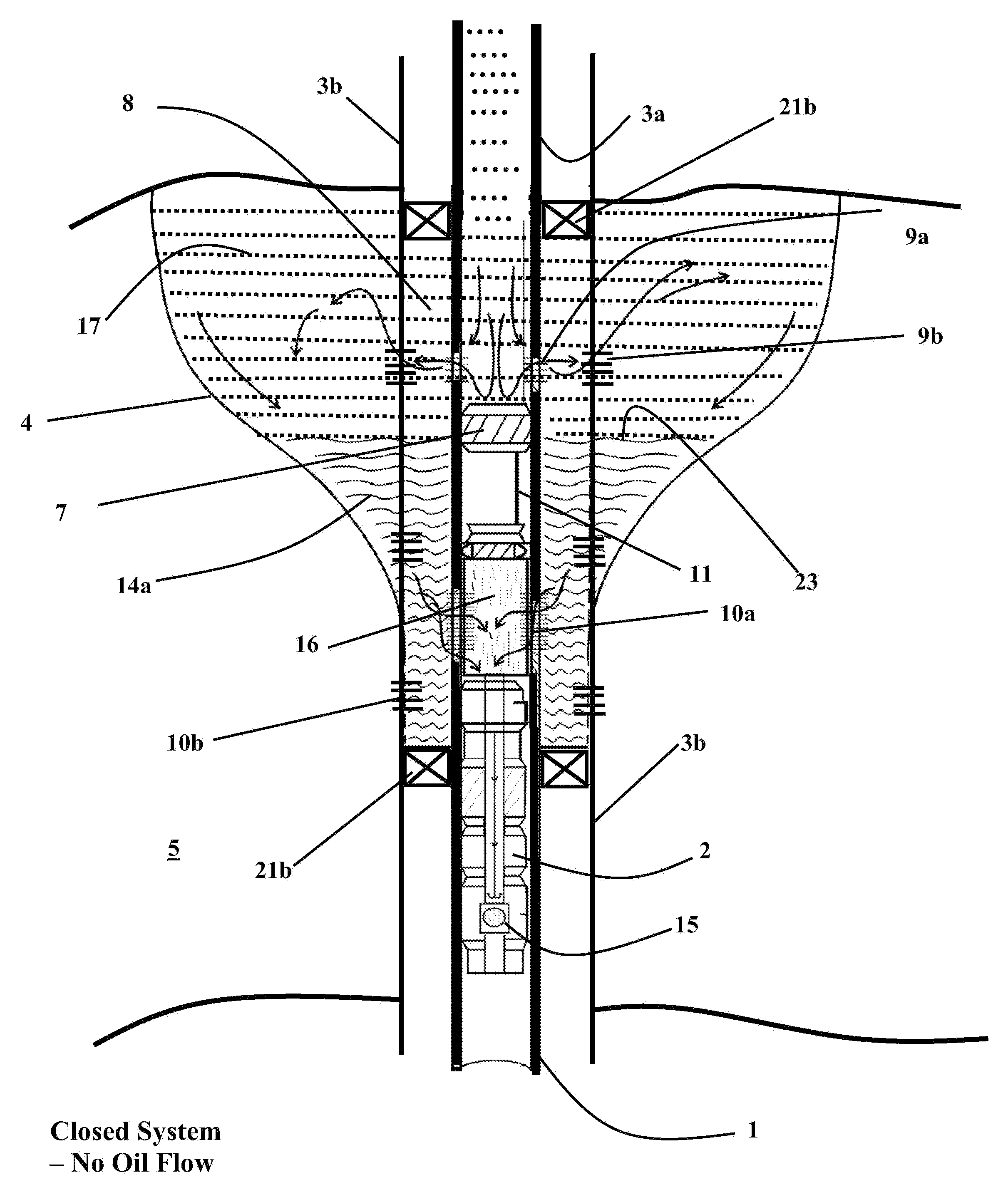
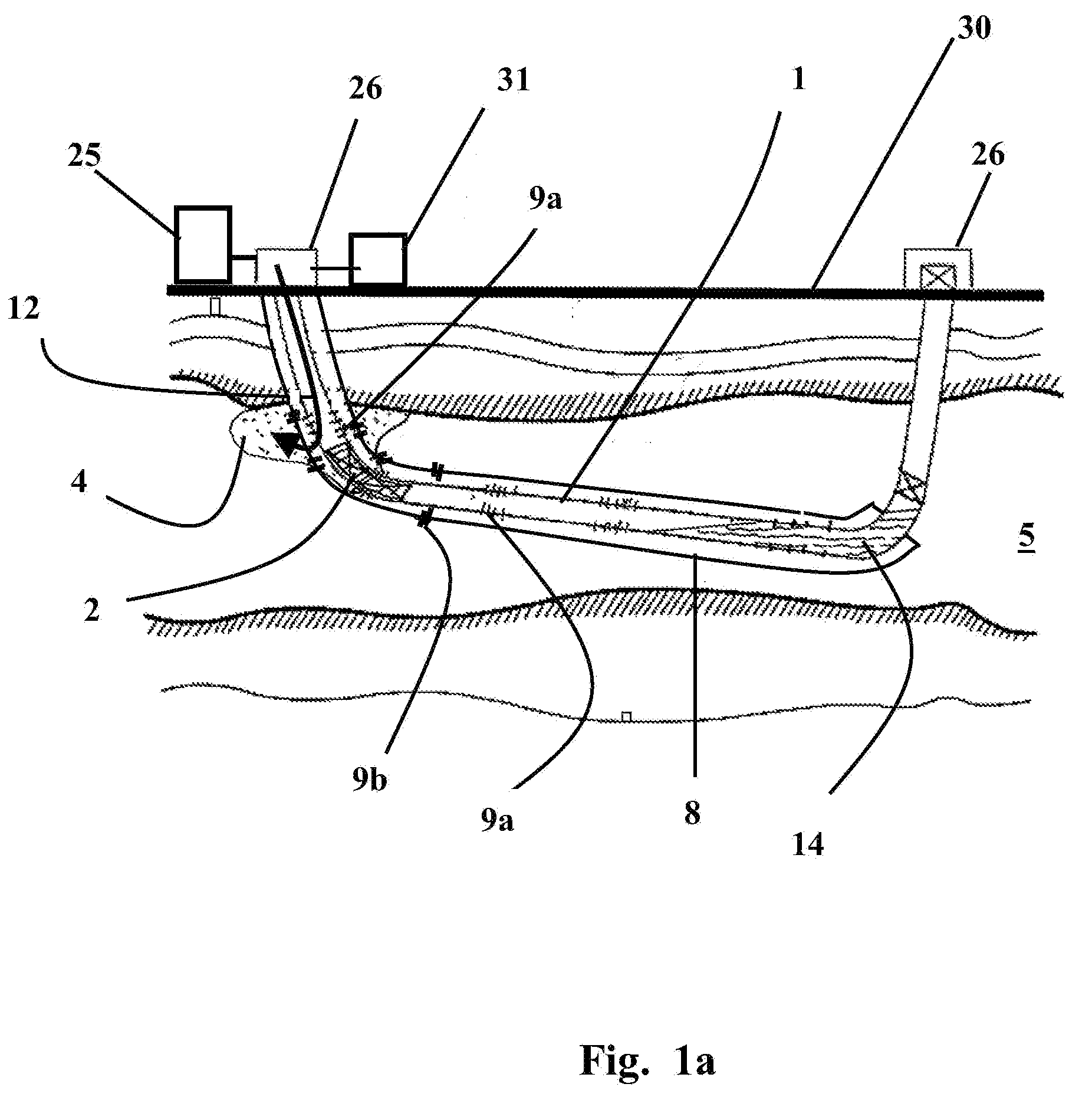
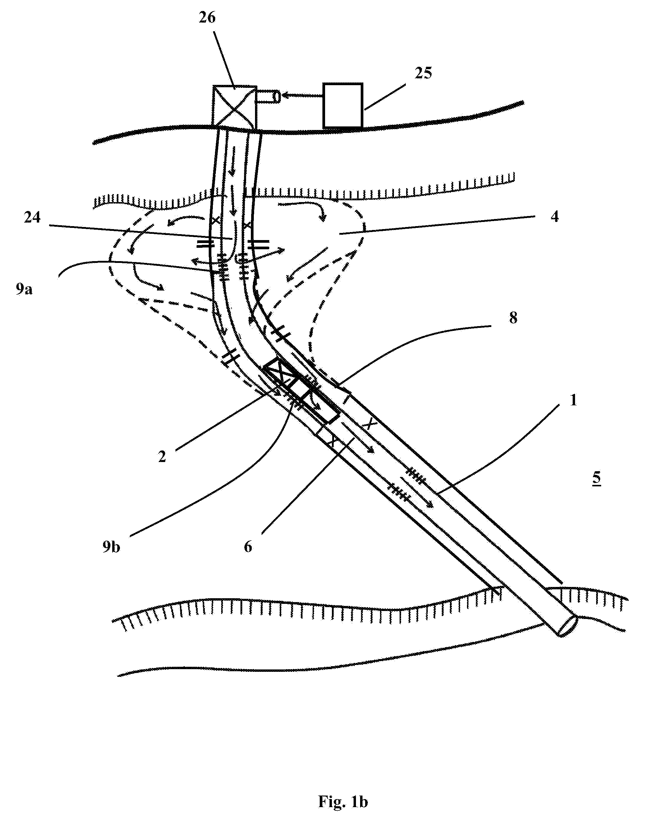
None of the devices used in the heavy oil recovery system by steam to date, examine the quality of the flowing fluid in the novel communication zone to discriminate its nature and thus
restrict flow based on this knowledge to maintain a
hydraulic seal.
The prior art applications do not adequately address this fact and as such are incapable of discriminating between hot oil, hot water and steam in the flow
stream and will be inadequate as controllers of steam flow and thereby reliable steam shut off mechanisms as are needed in heavy
oil field steam recovery operations.
The most significant oil recovery problem with heavy oil,
tar sands and similar hydrocarbonaceous material is the extremely high
viscosity of the native hydrocarbons.
This problem has continued to baffle the contemporary and prior art with possibly the only exception being the SAGD patent which uses two horizontal wellbores closely juxtaposed in a
vertical plane.
Even this SAGD approach has inherent difficulties in initiating the hot oil flow between the two wellbores.
In essence, this thermodynamically inefficient process is analogous to running an air conditioner and a heater simultaneously to maintain a room at a fixed temperature.
Further, even though the SAGD tries to utilize a limited
hydraulic seal as is described in this subject invention, the implementation in this subject
patent application is more precise, more operationally efficient and does not provide any detrimental effects on the overall steam process.
This heat loss lowers the overall recovery of the process.
Maintaining precise horizontal separation as well as the same
azimuth, between two lateral wellbores over several hundred feet and more than a thousand feet, is not easy and as such the SAGD process puts higher initial capital costs and difficult and stringent long term operational demands on the recovery process.
Another aspect of the SAGD process inefficiency is the need to inject steam in both injection and production wells for periods up to 415 days to “pre-heat” the reservoir and create a communication zone between the two wellbores.
Economically such a long
delay can severely
impact the economics of a capital project.
Another negative aspect of this SAGD process is the capital needs for drilling and equipping two
horizontal wells to implement the SAGD process.
Furthermore, the SAGD process requires a vertical separation between these two
horizontal wells and this property limits the SAGD process the relatively thick pay sections and cannot be used in thin reservoir sections.
A yet further limitation of SAGD is the effects of water zones at the base of the oil formation on the SAGD process since the steam preferentially enters the water zone and bypasses the cold
viscous oil zones.
This limits the thermal and economic efficiency of the SAGD process.
A yet further problem associated with the SAGD process is the presence of horizontal shale barriers in the oil formation.
This shale layer between the horizontal wellbores is in effect a vertical barrier and the SAGD process as designed and implemented is unable to operate since the two horizontal wells are unable to communicate.
These include:(1) the inability of the process to inject the hot fluid into a cold highly
viscous oil in a limited
conductivity formation with
hydrocarbon viscosities in excess of 106 cp, with this
viscosity the liquid is essentially immobile at reservoir temperature.
;(2) the inability of the method to prevent bypass of injected fluid directly from the
injector source towards the producing sink;(3) the inability of the method to form and maintain a viable communication zone from the steam zone or chamber to the producing sink while simultaneously preventing bypass and early breakthrough of steam;(4) the inability of the process to utilize the very effective
gravity drainage flow component created by the
low density of the hot steam compared to the relatively
high density condensed water and hot oil;(5) the inability of the process to heat the formation effectively by physical contact between the steam and the rock formation such that
latent heat, the major source of steam
heat energy, can be transferred to the rock and hydrocarbons efficiently;(6) the requirement of long lead times of months to years of hot
fluid injection, before there is any measurable production response of the displaced oil in the production wells;(7) the inability of the existing technology to maintain and sustain
oil production rates when applied to large patterns of several wells;(8) the inability of the downhole devices to determine flowing fluid characteristics other than temperature;(9) the inability of the technology to discriminate between flowing hot oil, hot water and steam in the flowing material;(10) the inability of the devices to operate based on the knowledge gained form these fluid characteristics;(11) finally the use of overly complex equipment of questionable
operational effectiveness to implement the process in the field.

