Method and apparatus for preventing or reducing color cross-talk between adjacent pixels in an image sensor device

a color cross-talk and image sensor technology, applied in the direction of radio frequency controlled devices, instruments, semiconductor devices, etc., can solve the problems of color cross-talk between adjacent pixels, more pronounced hue artifacts in the image, and artifacts in the final output image produced, so as to prevent or reduce the effect of reducing the occurrence of artifacts

Active Publication Date: 2009-07-07
PIXART IMAGING INC
View PDF1 Cites 2 Cited by
  • Summary
  • Abstract
  • Description
  • Claims
  • Application Information

AI Technical Summary

Benefits of technology

[0012]one or more shading structures configured to provide a predetermined shading pattern to control locations at which light impinges on the photodiode areas of the pixels. The predetermined shading patterns provide the pixels with substantially symmetrical angular responses to light and eliminate or reduce the occurrence of artifacts in the output image produced by the image sensor device.
[0013]The method comprises designing an IC to include one or more shading structures, and fabricating an IC based on the design to produce an IC having said one or more shading patterns. Each shading structure provides a predetermining shading pattern to thereby control the locations at which light impinges on photodiode areas of the pixels. The predetermined shading patterns provide the pixels with substantially symmetrical angular responses to light, thereby preventing or reducing the occurrence of artifacts in the output image produced by the image sensor device.

Problems solved by technology

This asymmetrical optical angular response often results in color cross-talk between adjacent pixels, i.e., light of one color bleeding over into a pixel intended to receive light of a different color.
This color cross-talk is problematic because it can lead to artifacts in the final output image produced by the image sensor device.
Furthermore, the asymmetrical angular response of pixels is even more pronounced in pixels located farther away from optical center of the imaging array, which can result in cross-talk amongst pixels closer to the optical center being unequal to cross-talk amongst pixels farther from the optical center.
This unequal cross-talk typically results in more pronounced hue artifacts in the image.

Method used


Image

  • Method and apparatus for preventing or reducing color cross-talk between adjacent pixels in an image sensor device
  • Method and apparatus for preventing or reducing color cross-talk between adjacent pixels in an image sensor device
  • Method and apparatus for preventing or reducing color cross-talk between adjacent pixels in an image sensor device

Examples


Embodiment Construction

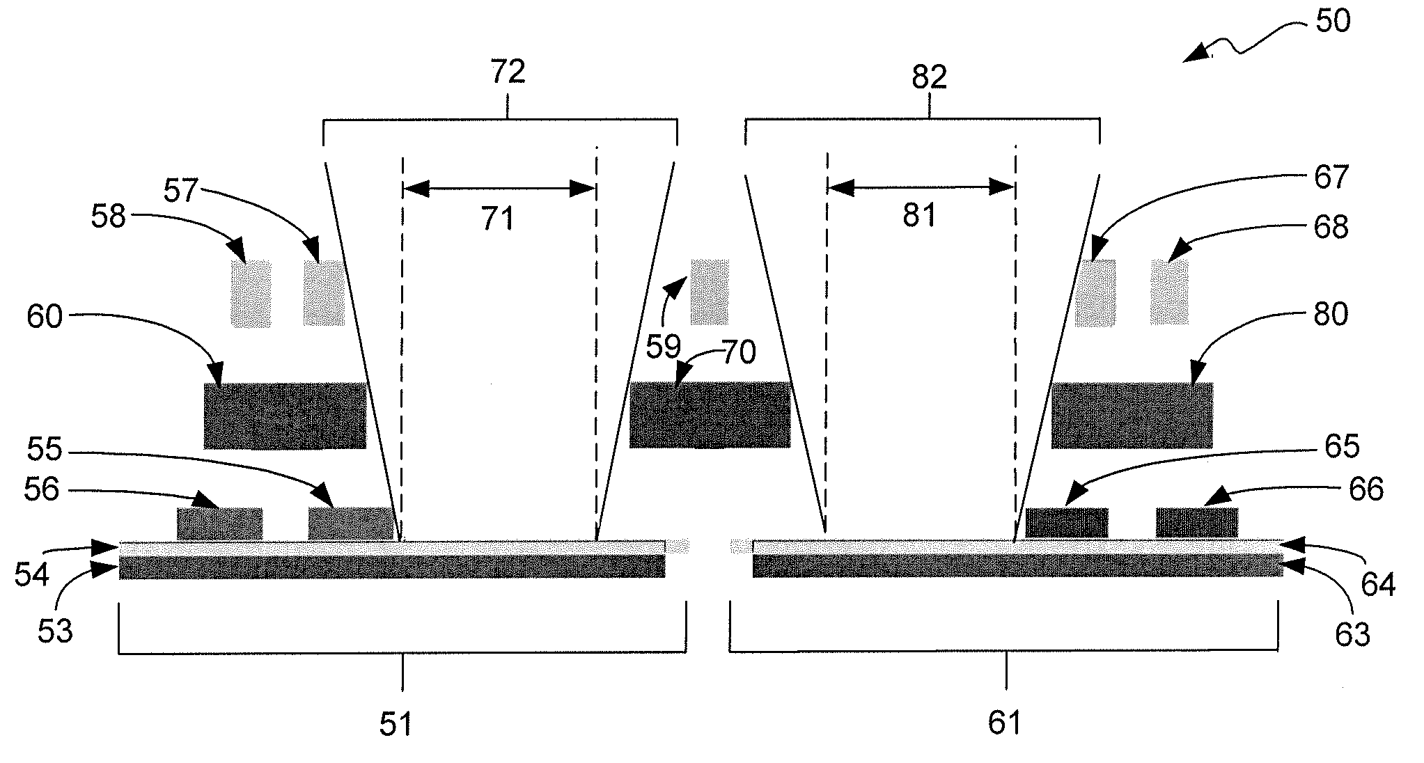
[0019]In accordance with the invention, one or more shading structures are used in the image sensor device to compensate for the non-normal angle of the incident light ray bundle, thereby making the angular response of the pixels more symmetrical. By making the angular response of the pixels more symmetrical, color cross-talk between adjacent pixels can be eliminated, or at least reduced. Making the angular responses of the pixels more symmetrical also eliminates or reduces the possibility of artifacts occurring in the output image of the image sensor device.

[0020]The structures that are used to make the angular response of the pixels more symmetrical include, for example, shading structures that are introduced into, or already existing in, the image sensor device that provide shading of light to control the locations at which light impinges on the photodiode area. The shading structures may have any number of shapes, including, but not limited to, slabs, stubs, square rings, circul...


PUM


Abstract

An image sensor device formed in an integrated circuit (IC) with one or more shading structures configured to provide a predetermined shading pattern to control the locations at which light impinges on the photodiode areas of the pixels. The predetermined shading patterns preventing color cross-talk and providing the pixels with substantially symmetric angular responses to light to thereby eliminate or reduce the occurrence of artifacts in the output image produced by the image sensor device.

Description

TECHNICAL FIELD OF THE INVENTION[0001]The invention relates to image sensor devices. More particularly, the invention relates to preventing or reducing color cross-talk between adjacent pixels in an image sensor device.BACKGROUND OF THE INVENTION[0002]An image sensor device is an integrated circuit (IC) having an array of pixels and circuitry for sampling the pixels and processing the pixel sample values. Pixel dimensions in image sensor devices are continually decreasing. At the same time, efforts are continually being made to increase the photodiode area of the pixels. One way to increase photodiode area is to share transistors that perform the same function amongst multiple pixels. Multiplexing devices and techniques are used in image sensor devices to allow these same-function transistors to be shared amongst multiple pixels. This pixel multiplexing makes it possible to increase full-well capacity, fill-factor, and sensitivity of the pixels, and thus to beneficially increase pho...

Claims


Application Information

Patent Timeline
Patent Type & Authority Patents(United States)
IPC IPC(8): H01L31/062H01L27/14H01L31/00H01L31/113H01L31/0232
CPCH01L27/14609H01L27/14623H01L27/14687H01L27/14685H01L27/14627H01L27/14625
Inventor GAZELEY, WILLIAM GEORGE
Owner PIXART IMAGING INC
Why Eureka
Try Eureka