Plastic injection molding machine and molding method

a technology of which is applied in the field of plastic injection molding machine and molding method, can solve the problems of defective mold closing, negative affecting the cycle time, and negatively affecting the opening time twofold

Active Publication Date: 2020-05-07
DISENO Y DESARROLLO DE MATRICERIA SL
View PDF0 Cites 1 Cited by
  • Summary
  • Abstract
  • Description
  • Claims
  • Application Information

AI Technical Summary

Problems solved by technology

They are voluminous machines that require considerable space for the placement thereof, and with elevated masses that must be put into motion when opening and closing the molds, which negatively affects the cycle time.
The greater the clamping force and the size of the platen, the more the deformations due to bending stress of these can increase and, as a result, the appearance of flash in the resulting pieces of a defective mold closing.
In this case, it is necessary for the total opening stroke to be double the individual opening stroke of each molding surface and negatively affects the opening time twofold, when comparing it to as it would be if the openings were made independent, for example by maintaining the central portion stationary and moving each of the sides.
Furthermore, the insertion of the molten polymer is generally done through the stationary platen, which causes great complexity when designing the supply of the mold, it being difficult to guarantee the same conditions of the material in the different portions of the mold and the molding surface being reduced and consequently reducing the numbers of figures.
Document U.S. Pat. No. 4,207,051 shows a type of construction in which the injection is carried out in the central portion, but requires the use of complex, expensive telescopic systems, or the withdrawal of the injection system each time the mold is opened.
Moreover, the pieces cannot be extracted until the mold opening movement has been completed.
Furthermore, the piece extraction is interrupted by the feed channel of the central portion, which would make the pieces collide with it.
All of these have either two rear platen with two mobile platen, in which case it relates to voluminous installations, or a single rear mobile platen with two mobile platen, in which case the mobile mass is increased, and furthermore also the time of the closing operation generally due to the fact that the closing strokes of the two mobile plates cannot be carried out simultaneously.
Furthermore, in this last case it always increases the length of the machine when the closing is produced due to the movement of the mobile rear platen.
In any of the embodiments, the tie bars are joined to one of the two mobile platens and therefore these swell the amount of mobile mass, increasing either the operation time and / or the energy consumption, in addition to the fact that the length of the machine is increased by the movement of the tie bar itself.
In all the previously cited cases, an additional problem is presented.
This causes the portions of the mold to not close perfectly together, giving rise to the formation of flash and defective pieces.
One of the disadvantages of this solution is that it requires a large mobile platen thickness in order for the geometry to work effectively.
Furthermore, a single geometry is not valid for the application of any clamping force, for which reason it is necessary to define a series of application ranges for each geometry.
The central portion does not only have rotation movement, it also has a very high mass that has to be moved linearly to be able to carry out the opening and closing, and this creates a large mass that must be put into motion, which negatively affects the cycle time and the energy consumption.
Furthermore, it requires having to complete the injection through the end plates, one of the units being placed in the mobile plate, which increases the mass to be moved even more.

Method used


Image

  • Plastic injection molding machine and molding method
  • Plastic injection molding machine and molding method
  • Plastic injection molding machine and molding method

Examples


first embodiment

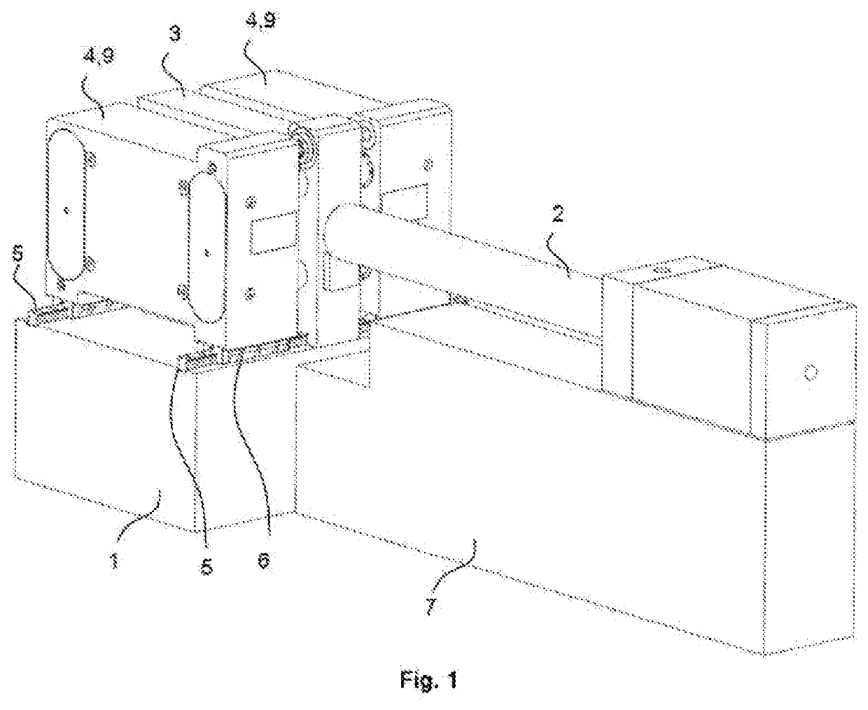
[0030]FIG. 1 shows a perspective view of the injection machine object of the present invention in a closed mold position.

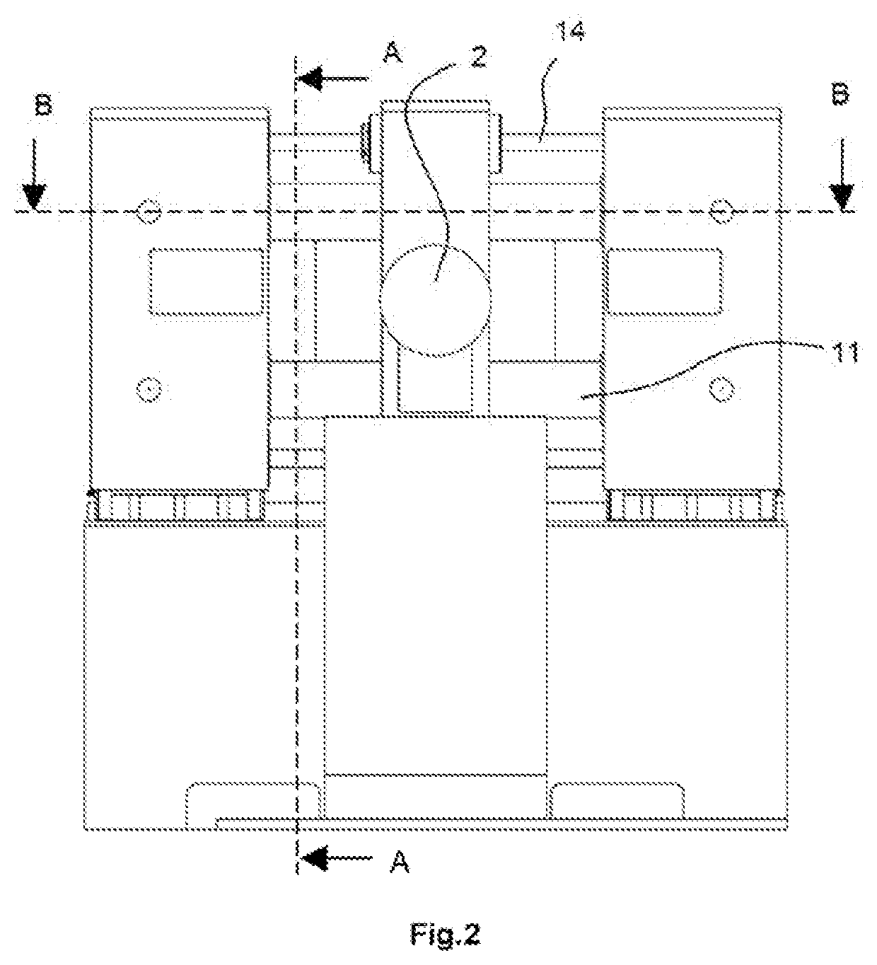
[0031]FIG. 2 shows a side view of the injection machine object of the present invention in an open mold position. The injection unit is partially shown for more clarity.

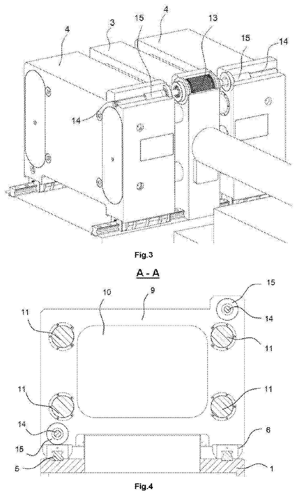
[0032]FIG. 3 shows a perspective view with a detail of a partial cross section of the actuation of a first movement system for the embodiment of the opening and closing movement of the mobile platens.

[0033]FIG. 4 shows an elevation view of a cross section A-A, according to FIG. 2, in which the face of the mobile platen is seen from the stationary central platen.

[0034]FIG. 5 shows a schematic cross section that shows the elements that are involved in the closing of the mold, according to the cross section B-B turned 90° indicated in FIG. 2. Some elements have been drawn with an intentionally large deformation in order to create a clearer description of the system.

[0035]FIG. 6 shows a transverse cros...

second embodiment

[0037]FIG. 8 shows the invention according to a general view of the injection machine object of the present invention in a closed mold position and with the injection and plasticization unit with the axis parallel to the opening and closing direction of the molds.

third embodiment

[0038]FIG. 9 shows a detail of a perspective view of the invention with the actuation of a second example of a movement system for carrying out the opening and closing movement of the plates.


PUM

PropertyMeasurementUnit
rotationaaaaaaaaaa
pressureaaaaaaaaaa
clamping forceaaaaaaaaaa

Abstract

A plastic injection molding machine and molding method related to an injection molding machine for stack molds, wherein the central portion of the mold remains fixed and it has two molding faces that act on the fixed central portion by means of a hydraulic chamber that produces the clamping force and prevents the deformations due to bending on the molding faces. Likewise, it relates to a molding method.

Description

APPLICATION FIELD OF THE INVENTION[0001]The present invention relates to a machine for manufacturing plastic pieces for the injection molding method that improves the systems that use injection molding machines for the use thereof with simple or stack molds, as well as the molding method. More specifically, the machine object of the invention is of special application in the manufacturing of large series of pieces for the packaging, food, health etc. sectors, using multi-cavity molds, as well as in smaller series of pairs of pieces, the shape of which is approximately symmetrical, such as, for example, front and back bumpers, or left and right door panels, for the automobile sector, among others.[0002]The invention falls within the field of machinery for injection molding of plastic components.DESCRIPTION OF THE STATE OF THE ART[0003]Generally, plastic injection molding machines have a stationary platen and a mobile platen, upon which each of the two halves that make up the mold are...

Claims


Application Information

Patent Timeline
Patent Type & Authority Applications(United States)
IPC IPC(8): B29C45/32B29C45/04B29C45/68B29C45/17B29C45/50
CPCB29C45/5008B29C45/32B29C45/1761B29C2045/5028B29C45/1744B29C2045/688B29C45/045B29C45/68B29C2045/1764B29C45/67B29C45/6707B29C45/683B29C2045/665B29C2045/675
Inventor PACIOS RIVERA, JOSE ANTONIO
Owner DISENO Y DESARROLLO DE MATRICERIA SL
Why Eureka
Try Eureka