Bridge particularly for crossing a passage of a navigation channel

a navigation channel and bridge technology, applied in the field of bridges, can solve problems such as occupying a large space in the structure of bridges, and achieve the effect of reducing the need for structur

Inactive Publication Date: 2009-07-07
SOC EURO DINGENIERIE MECANIQUE EURODIM SA
View PDF29 Cites 5 Cited by
  • Summary
  • Abstract
  • Description
  • Claims
  • Application Information

AI Technical Summary

Benefits of technology

[0009]According to yet another characteristic of the invention, the means for lifting the span entail a balance arm mounted to pivot on a support structure from one end of which the span is suspended, whereas some pivoting actuation means are connected at the other end.
[0010]According to yet another characteristic of the invention, the span is a self-supporting structure suspended from the end of the balance arm by suspension cables.
[0011]According to yet another c

Problems solved by technology

Bridges of this type that are known have the major disadvantage of having a complex structure requiring much space, inasmuch as they have, on each side of the channel, a support structure that requires extensive ins

Method used


Image

  • Bridge particularly for crossing a passage of a navigation channel
  • Bridge particularly for crossing a passage of a navigation channel
  • Bridge particularly for crossing a passage of a navigation channel

Examples


first embodiment

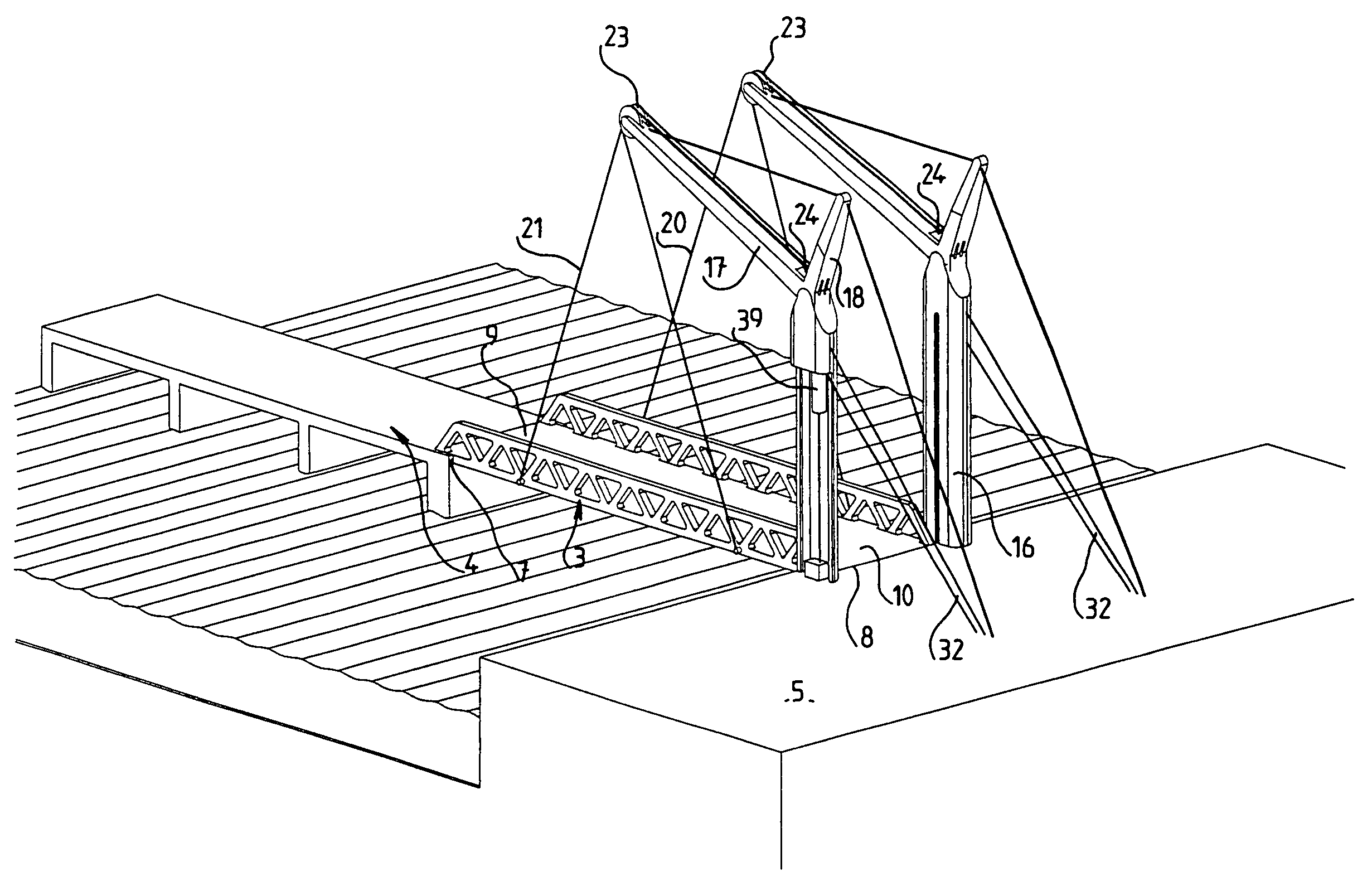
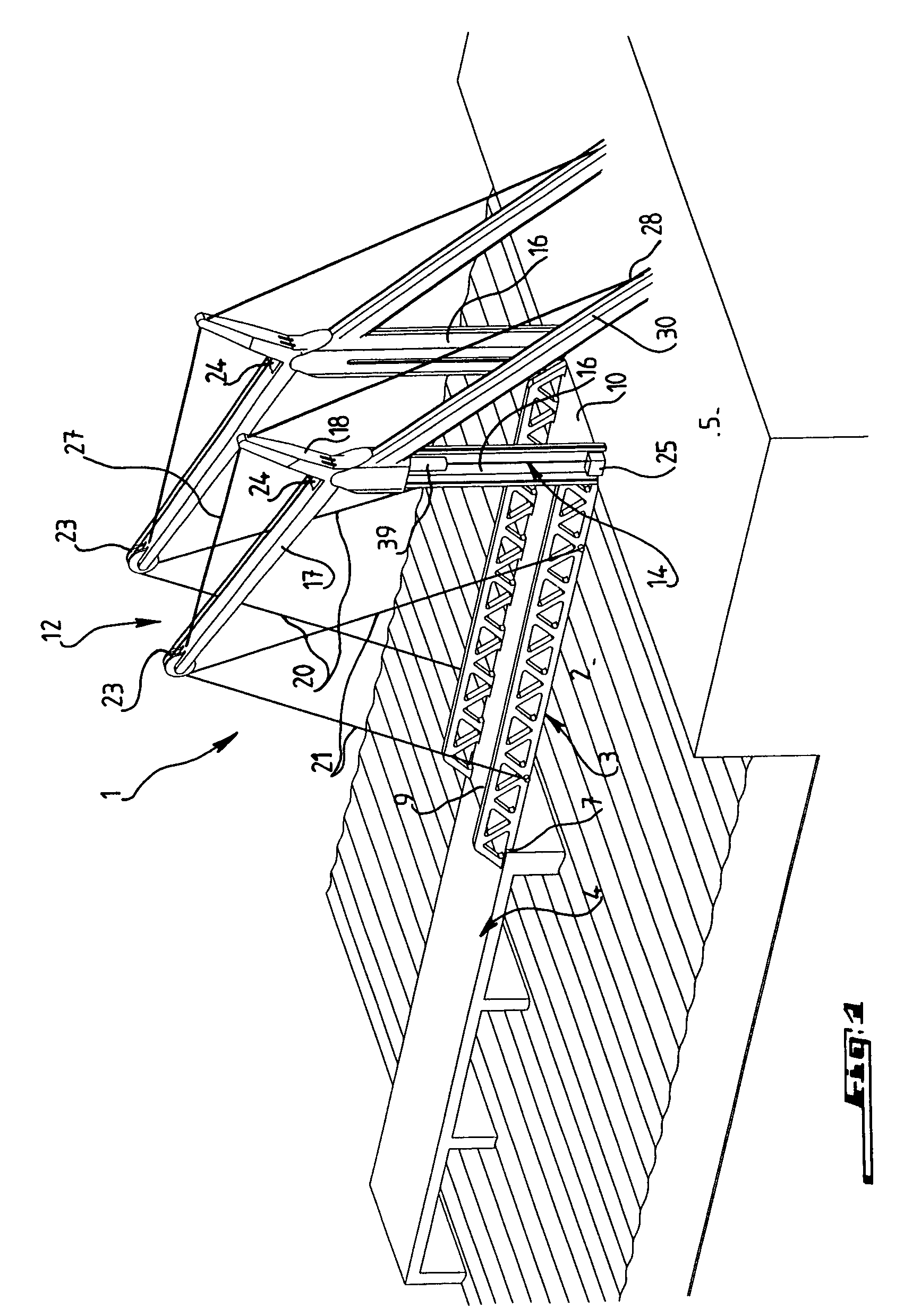
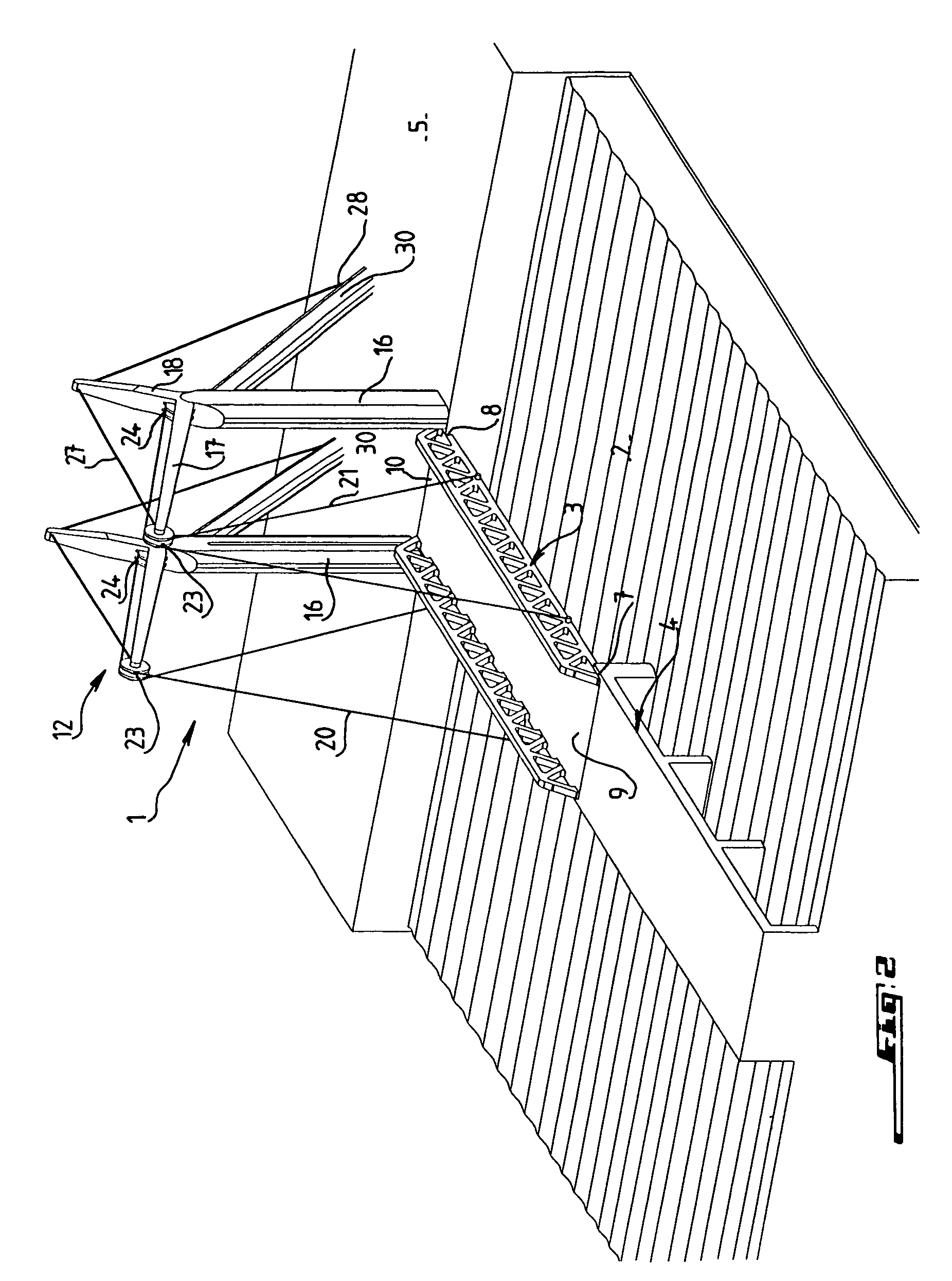
[0028] represented in FIGS. 1-6, support structure 12 is stationary and essentially includes, on each lateral side of span 3, vertical pylon 16 anchored at its lower end in stationary bank part 5 and which bears, at its upper end, girder 17 extending from the pylon, inclined upward, up to approximately the middle of span 2, and girder 18 extending upward at approximately a right angle with respect to girder 17.

[0029]Span 3 is suspended mainly during lifting from the free end of each girder 17 by the intermediary of two lifting cables 20, 21 fastened through an end of span 3 and running over pulley 23 mounted on the end of girder 17, along this girder, over another pulley 24 situated at the top of the pylon, and then inside of pylon 16 to traction device 25 arranged at the foot of this pylon. This device could be a winch for winding or unwinding of lifting cables 20, 21, or any other suitable traction device such as a jack. In order to ensure the horizontal position of span 3, each l...

second embodiment

[0035]FIGS. 7-15 illustrate several versions of a bridge according to the invention.

[0036]This second embodiment is characterized by the fact that the lifting of span 3 is ensured by the tilting of balance arm 42 mounted so as to pivot at the top of pylons 16. The pivoting of the balance arm takes place on rotational bearings, pivot pins, hard bearing or any other tilting mechanism. This balance arm is formed by two two-armed levers 43 connected together, for example, by crosspiece 45 at the ends of front arms 44, from which span 3 is suspended by suspension cables 46, whereas at each free end of rear arm 44′, whose length can be different from that of the front arm, traction cables 48 are connected, actuated by a traction device of any appropriate nature such as winches or jacks 50. This traction device can be associated with a device for anchoring of the balance arm in stationary part 5, such as cables, bars, or portals, which immobilizes the tilting of the balance arm when the sp...


PUM


Abstract

A bridge for crossing a passage of a navigation channel includes a section in the form of a single span, which may be displaced by vertical translation between a base position spanning the passage, in which the span rests on fixed support sections of the bridge, and a raised position, for opening the passage, and a support structure for the span on displacement of the span, and a drive for lifting the span. The bridge has only one support structure, with the drive, located on one side of the passage to be spanned.

Description

FIELD OF INVENTION[0001]The invention relates to a bridge intended in particular for crossing a channel of a waterway and having a part in the form of a span, which can be moved by vertical translation between a low position for crossing the channel, in which the span rests on stationary support parts of the bridge, and a high position for opening the channel, and a support structure for the span during its movement as well as some means for lifting the span.BACKGROUND[0002]Bridges of this type that are known have the major disadvantage of having a complex structure requiring much space, inasmuch as they have, on each side of the channel, a support structure that requires extensive installation work particularly when the structure is in the water, and that must be equipped with lifting means that must be powered and perfectly coordinated, which requires sophistication in the design of these means.SUMMARY OF THE INVENTION[0003]The present invention provides a bridge that does not hav...

Claims


Application Information

Patent Timeline
IPC IPC(8): E01D15/02
CPCE01D15/02E01D18/00
Inventor GHILARDI, JEAN-PIERRE
Owner SOC EURO DINGENIERIE MECANIQUE EURODIM SA
Why Eureka
Try Eureka