Automated loader

a loader and automatic technology, applied in the field of automatic container handling system, can solve the problems of frequent maintenan

Active Publication Date: 2009-07-14
MCNEILUS TRUCK & MFG INC
View PDF16 Cites 102 Cited by
  • Summary
  • Abstract
  • Description
  • Claims
  • Application Information

AI Technical Summary

Benefits of technology

[0010]The spaced lift support members are mounted so as to pivot in a generally vertical plane relative to the upper cross member and the lower portion of the lift support members are further pivotally attached to a bottom extending frame that includes a pair of spaced, generally parallel, laterally extendable members connected to advance and retract the lower portion of the lift support members thereby causing the upper ends of the lift support members to pivot and the vertical support members to telescope to accommodate the corresponding vertical displacement of frame members thereby accommodating the generally linear lateral displacement of the lower portions. In this manner, the associated container grabber can remain generally at the same height during lateral displacement.
[0011]A carriage system is mounted from the lift support members and carried by a drive system in a manner that enables it to traverse along the lift support members to accomplish a lifting function. The carriage system includes a rotary actuator having a double ended output including output shafts that carry and rotate spaced arm members of a yoke which, in turn, is fixed to a grabbing device for grabbing and releasing containers. The yoke mount enables the grabbing device to be pivoted or rotated generally vertically about a very short radius so as to rotate from a storage to a grabbing or deployed position in limited lateral space and also to adjust the posture of a grabbed container throughout a lift and dump cycle. The grabbing device is preferably one with opposed spaced fingers that close about a container during the grabbing function and open to release the container. The fingers are preferably operated by a compact, fully enclosed hydraulic actuating system that rotates spaced mounting shafts to open and close the fingers. The grabber fingers are designed to accommodate a wide range of container shapes and sizes.
[0012]The carriage is operated along the lift support members by a chain and cylinder mechanism that includes a pair of double-acting, double-ended hydraulic lift cylinders, each operating along a cylinder rod mounted along an associated lift support member in conjunction with a chain carried by sprockets mounted at the ends of each of the lift cylinders in coordinated fashion to operate the carriage and with it the grabber system along the lift support members to raise and lower a captured container. The rods are approximately twice the length of the cylinders. The carriage system is attached to mounts carried by the chains which are also fixed to the lift support members near the midpoints thereof in a manner that enables the carriage to travel the full length of the rods or lift support members or double the distance traveled by the lift cylinders as the chains also move the carriage a distance equal to that traveled by the cylinders.

Problems solved by technology

Mechanisms of known container handling devices generally have a large number of moving parts and articulated joints which are exposed to the extreme clogging and corrosive conditions of refuse collection, and, as such, tend to require frequent maintenance.

Method used


Image

  • Automated loader
  • Automated loader
  • Automated loader

Examples


Embodiment Construction

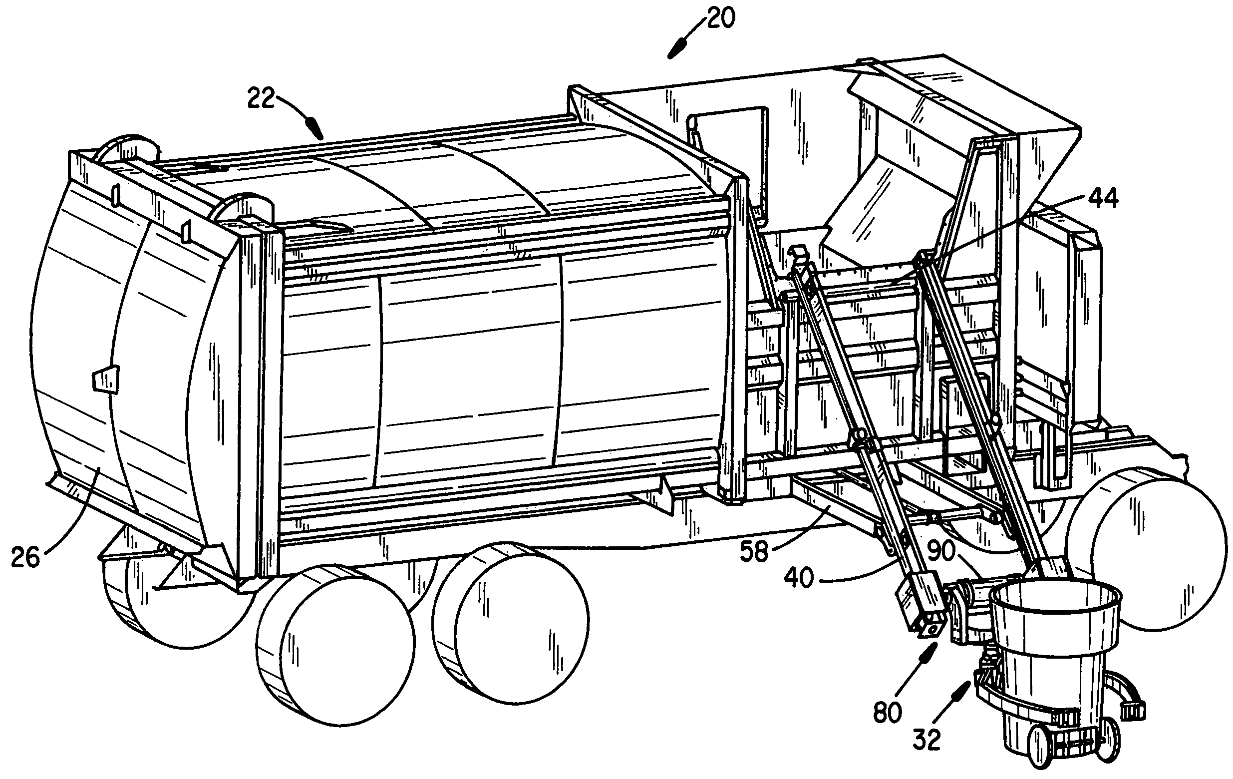
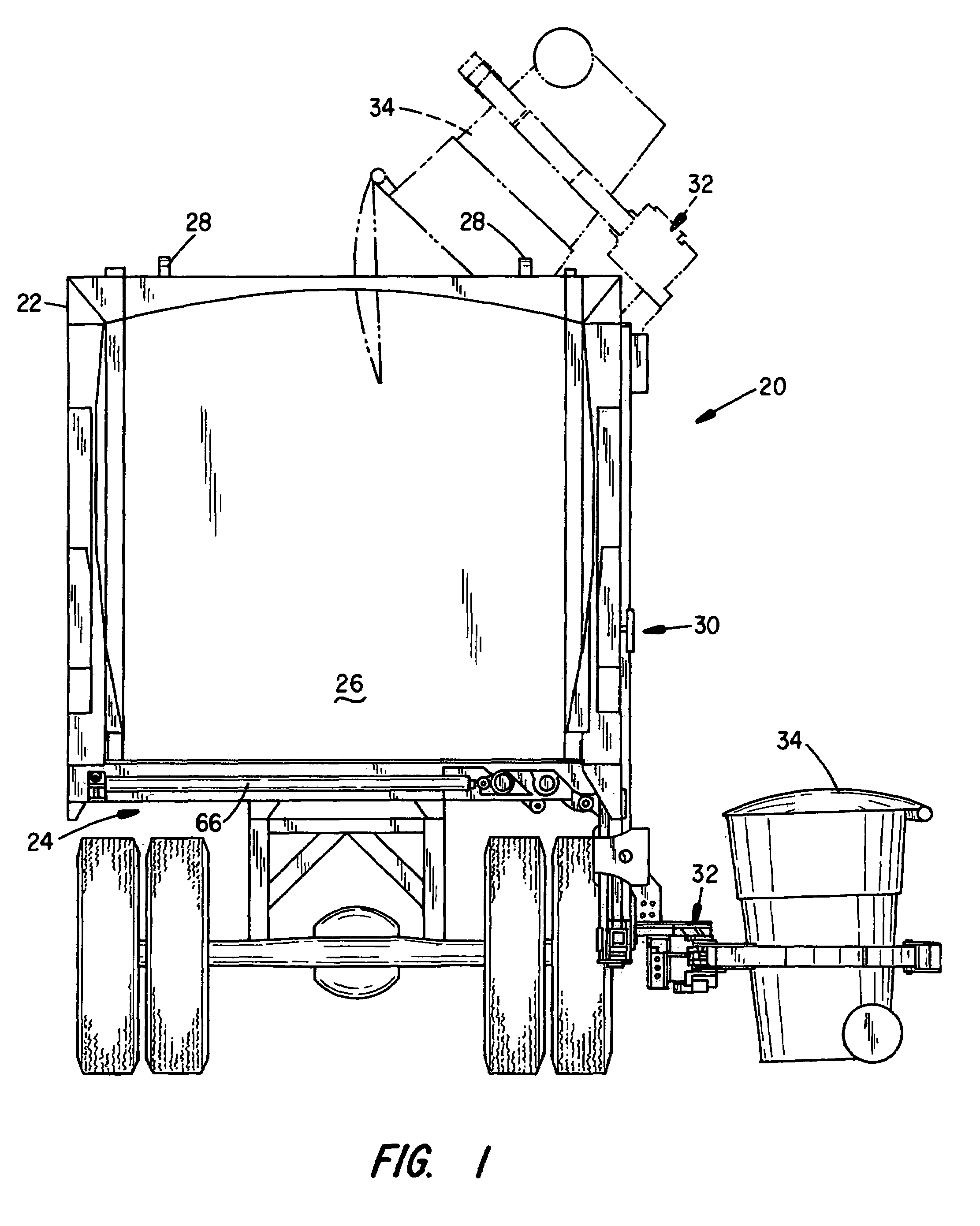
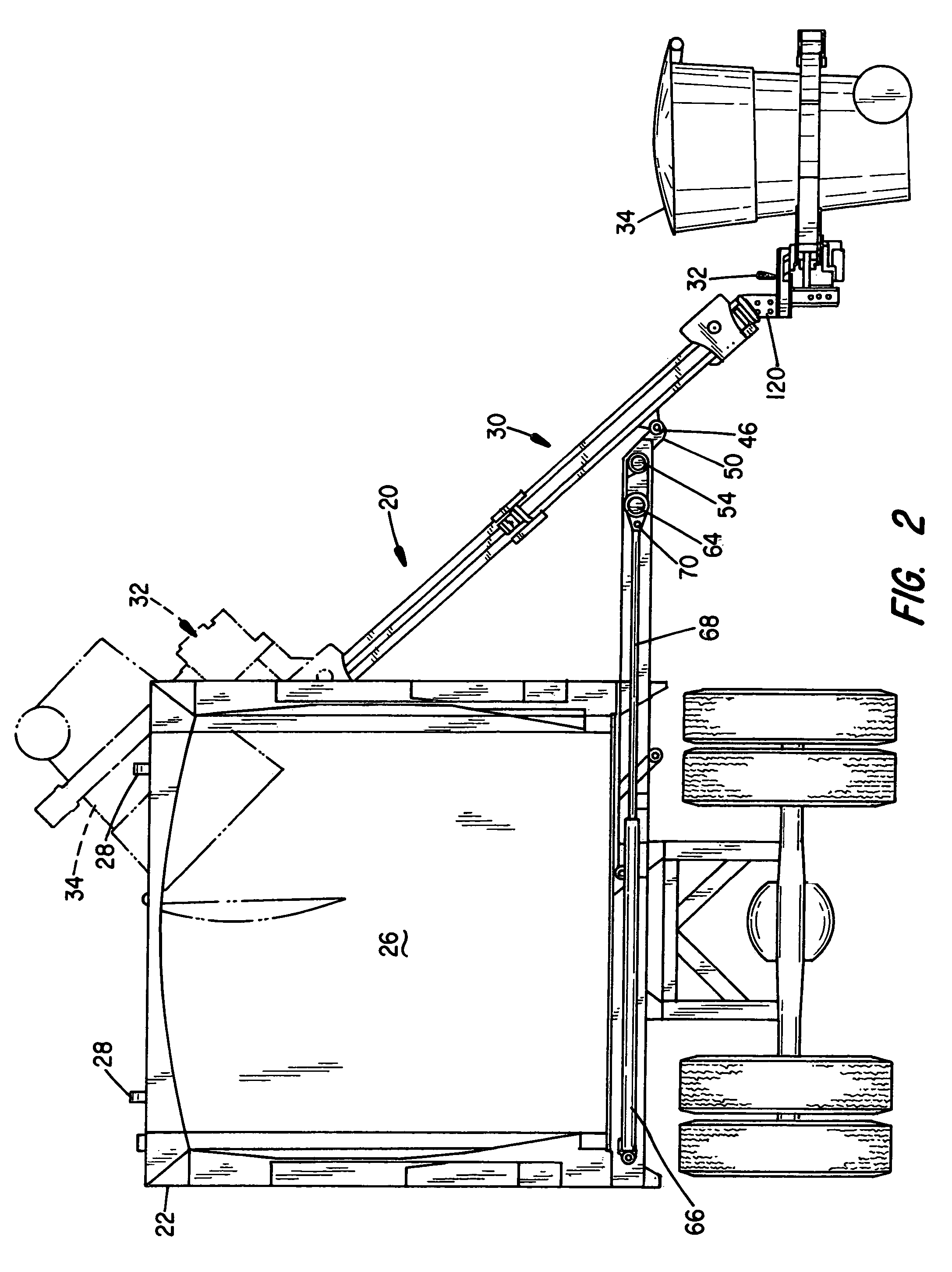
[0024]The container handling system of the present invention represents advances in the automated lifting and emptying of containers, particularly with regard to manipulating containers in close quarters and addressing a wide variety of container sizes and weights. The system enables the lifting and tipping of containers with little or no lateral room in a manner which also enables the containers to remain generally upright throughout the grabbing and lifting process until the final tipping. The system greatly reduces the need for lateral and vertical space associated the lift and tip operations.

[0025]The container handling system is able to handle containers in a wide range of sizes and shapes including large, heavy containers. For example, such a system handles anything from normal 34 gallon (129 liter) residential curb-side containers to much larger containers such as 300 gallon (1136 liter) containers weighing 1200 pounds (544.2 kg) or more. The entire operation of the system ma...


PUM


Abstract

A container handling mechanism suitable for mounting on the side of a refuse vehicle for loading material from refuse containers is disclosed that includes a lift assembly, having a pair of spaced, generally parallel lift support members, attachable to a refuse vehicle, a carriage device reciprocally operable along the lift support members of the lift assembly, a container grabbing system carried by the carriage device and further including a pair of opposed grabber fingers and an actuator system for closing and opening the grabber fingers to engage and release containers of interest, the container grabbing system being vertically pivotable on a short radius for adjusting the position of and tipping a container. A chain and cylinder drive system operates the carriage device along the lift assembly, and a control system controls operation of the container handling mechanism.

Description

BACKGROUND OF THE INVENTION[0001]I. Field of the Invention[0002]The present invention relates generally to container handling equipment, including systems for accessing, grabbing, lifting and tipping a wide range of sizes and shapes of collection containers into charging hoppers or compartments of side loading collection vehicles, or other receptacles, and thereafter returning empty containers to their pickup locations. More particularly, the present invention relates to an automated container handling system including a container grabbing device, that is not only capable of lateral extension, but also capable of full lift and dump operation in very close quarters. A linearly-operating lift system is provided to lift and lower containers that cooperates with a pivoting, short-arm container grabbing device with hydraulic fingers. A rotary actuator pivots the grabbing device to adjust grabbing angle, tip containers and rotate it to and from a stowed position.[0003]II. Related Art[0004...

Claims


Application Information

Patent Timeline
Patent Type & Authority Patents(United States)
IPC IPC(8): B65G65/23
CPCB65F3/046B65F3/08B65F2003/0276B65F2003/0266B65F2003/023
Inventor PRUTEANU, CLAUDIU D.MELDAHL, BRIAN R.BICE, RANDALL L.GILLARD, JASON M.
Owner MCNEILUS TRUCK & MFG INC
Why Eureka
Try Eureka