Medical wireless imaging device
a wireless imaging and medical technology, applied in the field of image sensors, can solve the problems of insufficient illumination of the subject for imaging, insufficient requirements for imaging, and only providing flat images, and achieve the effects of simple and cost-effective manufacturing, reduced size and reduced cos
- Summary
- Abstract
- Description
- Claims
- Application Information
AI Technical Summary
Benefits of technology
Problems solved by technology
Method used
Image
Examples
first embodiment
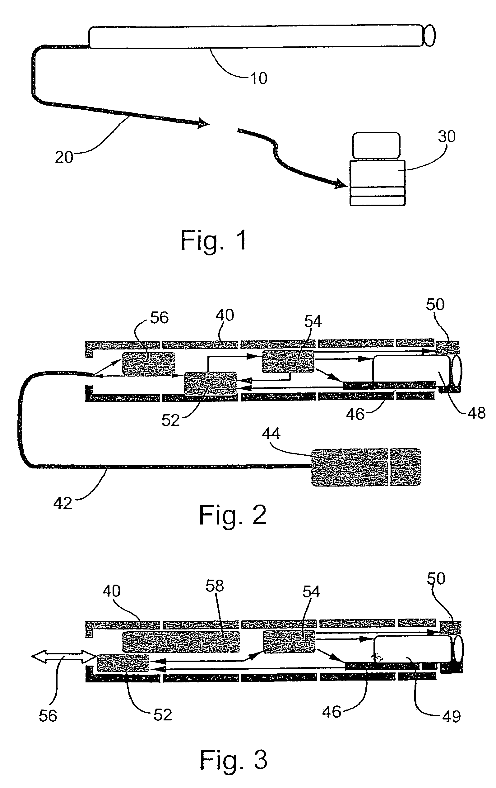
[0154]Reference is now made to FIG. 1, which is a basic block diagram of a basic configuration of an endoscope according to the present invention. The figure shows a basic configuration of the endoscopic system including interconnections. The configuration comprises a miniature endoscopic front-end 10, hereinafter simply referred to as an endoscope, attached by a wire connection 20 to a processing device 30, typically a PC, the PC having appropriate software for carrying out image processing of the output of the endoscope. The skilled person will appreciate that the wire connection 20 may be an optical connection or may instead use RF or a like means of wireless communication. The miniature endoscopic front-end 10 may be designed for connection to any standard PC input (the USB input for example).
[0155]The software included with processing device 30 processes the output of the miniature endoscopic front-end 10. The software may typically control transfer of the images to the monitor...
third embodiment
[0188]Reference is now made to FIG. 8, which is a ray diagram showing the optical assembly 48, this time for the second of the specific embodiments of the image sensor 46, namely the embodiment in which the square shape of pixels is reduced to a rectangular shape having smaller width. An asymmetric or astigmatic lens 92 is arranged to focus light onto a front-surface-mirror 94. The light is distorted by the lens 92 to undo the distortion introduced into the image by the rectangular shape of the sensor 46, and then it is reflected by the mirror 94 onto the surface of the sensor 46.
[0189]Reference is now made to FIG. 9, which is a ray diagram taken from the side showing a further embodiment of the optical assembly 48. The embodiment of FIG. 8 necessitates a relatively complicated design of the mirror, and in order to obviate such complexity, additional optical design is shown. As shown in FIG. 9, the same astigmatic lens 92 is placed, not in front of a mirror but rather in front of a ...
PUM
 Abstract
Description
Claims
Application Information
 - R&D
- Intellectual Property
- Life Sciences
- Materials
- Tech Scout
- Unparalleled Data Quality
- Higher Quality Content
- 60% Fewer Hallucinations
Browse by: Latest US Patents, China's latest patents, Technical Efficacy Thesaurus, Application Domain, Technology Topic, Popular Technical Reports.
© 2025 PatSnap. All rights reserved.Legal|Privacy policy|Modern Slavery Act Transparency Statement|Sitemap|About US| Contact US: help@patsnap.com


