Image-distorting endoscopes and methods of making and using such endoscope

a technology of endoscope and image distortion, which is applied in the field of image sensors, can solve the problems of insufficient illumination of the subject for imaging, insufficient requirements for image quality, and insufficient two-dimensional images, etc., and achieve the effects of simple and cost-effective manufacturing, reduced size and reduced siz

Inactive Publication Date: 2007-07-10
GYRUS ACMI INC (D B A OLYMPUS SURGICAL TECH AMERICA) +1
View PDF91 Cites 36 Cited by
  • Summary
  • Abstract
  • Description
  • Claims
  • Application Information

AI Technical Summary

Benefits of technology

[0019]It is an aim of the embodiments to provide an endoscope that is smaller than current endoscopes but without any corresponding reduction in optical processing ability.
[0116]According to an eighth embodiment of the present invention there is provided a compact endoscope for producing 3D images of a field of view, comprising two illumination sources for illuminating said field of view, an image sensor for receiving a view of said field illuminated via each of said illumination sources, and a view differentiator for differentiating between each view.

Problems solved by technology

However, most current endoscopes provide only flat, two-dimensional images which are not always sufficient for the requirements of the surgery.
An additional problem with current endoscopes is the issue of lighting of the subject for imaging.
The above-mentioned solutions are however incomplete and are difficult to integrate into a single endoscope optimized for all the above issues.

Method used


Image

  • Image-distorting endoscopes and methods of making and using such endoscope
  • Image-distorting endoscopes and methods of making and using such endoscope
  • Image-distorting endoscopes and methods of making and using such endoscope

Examples


first embodiment

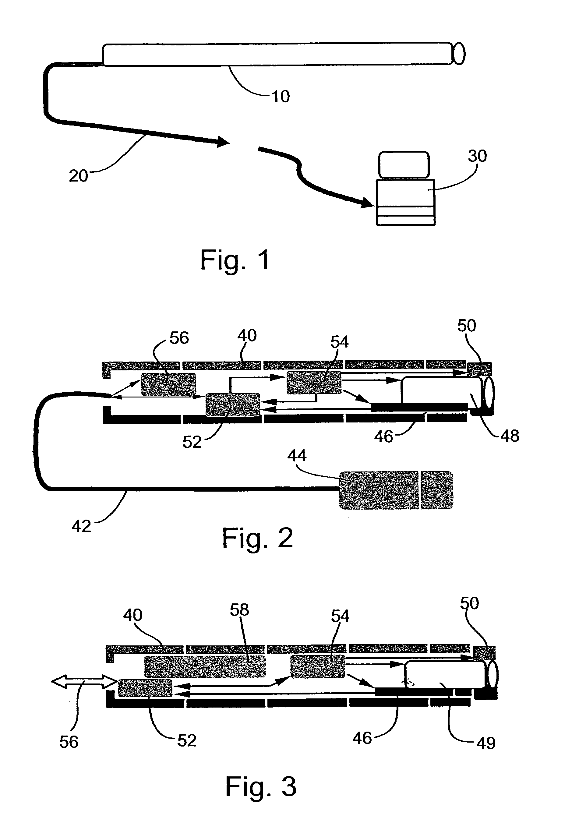
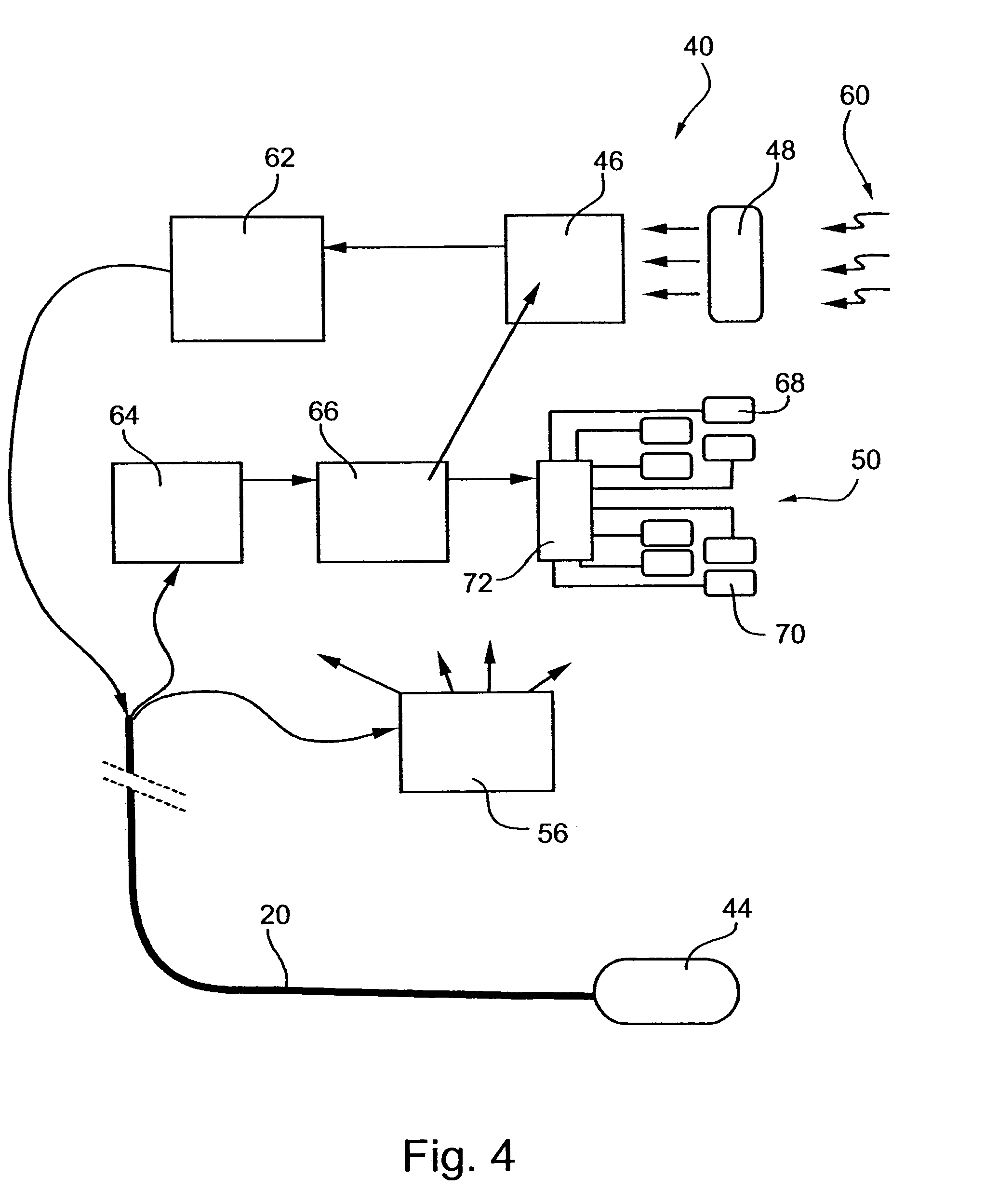
[0154]Reference is now made to FIG. 1, which is a basic block diagram of a basic configuration of an endoscope according to the present invention. The figure snows a basic configuration of the endoscopic system including interconnections. The configuration comprises a miniature endoscopic front-end 10, hereinafter simply referred to as an endoscope, attached by a wire connection 20 to a processing device 30, typically a PC, the PC having appropriate software for carrying out image processing of the output of the endoscope. The skilled person will appreciate that the wire connection 20 may be an optical connection or may instead use RF or a like means of wireless communication. The miniature endoscopic front-end 10 may be designed for connection to any standard PC input (the USB input for example).

[0155]The software included with processing device 30 processes the output of the miniature endoscopic front-end 10. The software may typically control transfer of the images to the monitor...

third embodiment

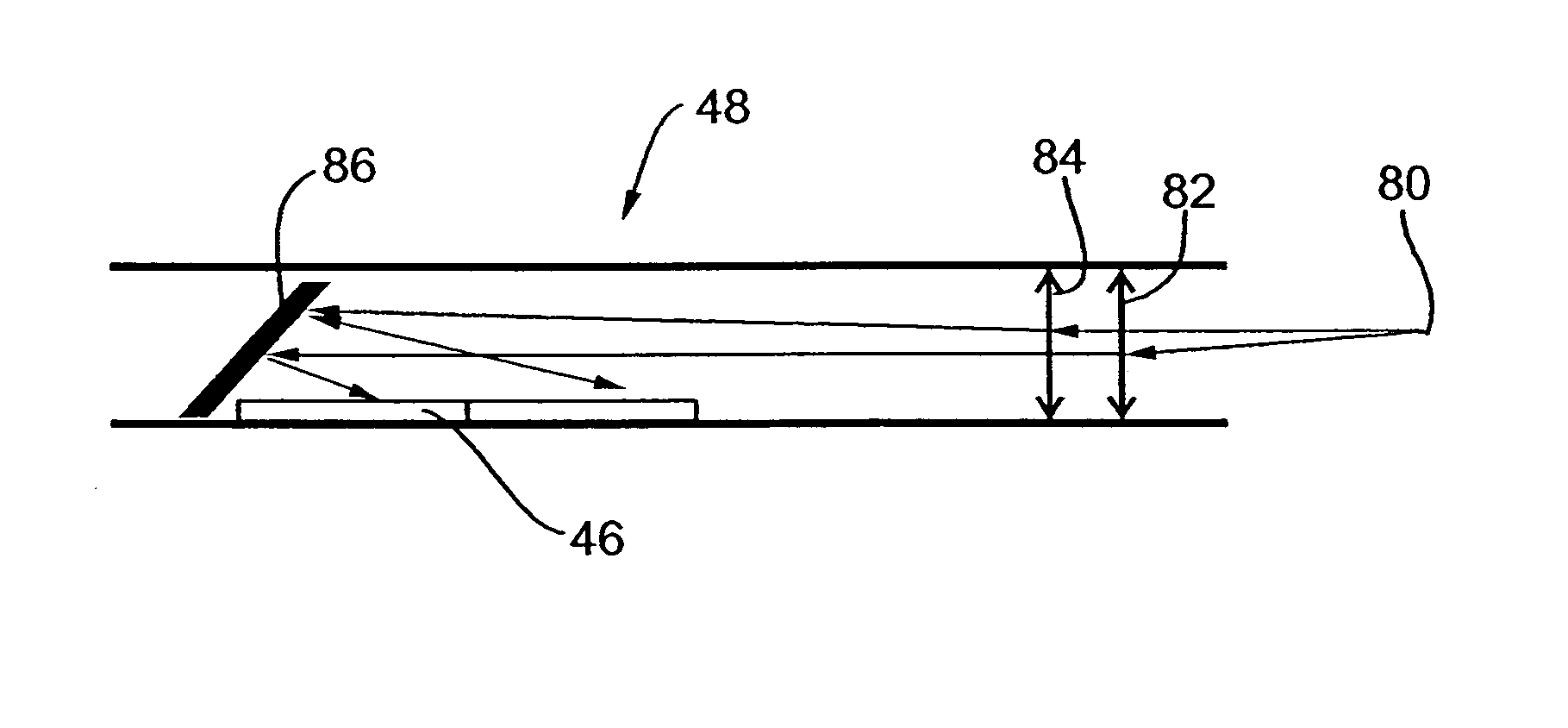
[0187]Reference is now made to FIG. 8, which is a ray diagram showing the optical assembly 48, this time for the second of the specific embodiments of the image sensor 46, namely the embodiment in which the square shape of pixels is reduced to a rectangular shape having smaller width. An asymmetric or astigmatic lens 92 is arranged to focus light onto a front-surface-mirror 94. The light is distorted by the lens 92 to undo the distortion introduced into the image by the rectangular shape of the sensor 46, and then it is reflected by the mirror 94 onto the surface of the sensor 46.

[0188]Reference is now made to FIG. 9, which is a ray diagram taken from the side showing a further embodiment of the optical assembly 48. The embodiment of FIG. 8 necessitates a relatively complicated design of the mirror, and in order to obviate such complexity, additional optical des is shown. As shown in FIG. 9, the same astigmatic lens 92 is placed, not in front of a mirror but rather in front of a ser...


PUM


Abstract

An endoscope having restricted dimensions and comprising at least one image gatherer, at least one image distorter and at least one image sensor shaped to fit within said limited dimensions, and wherein said image distorter is operable to distort an image received from said image gatherer so that the image is sensible at said shaped image sensor.

Description

RELATED PATENT APPLICATIONS[0001]This application is a Divisional Patent Application of U.S. Application Ser. No. 09 / 826,163 filed Apr. 5, 2001, now U.S. Pat. No. 6,659,940, which claims priority from Israel Patent Application No. 135571 filed Apr. 10, 2000.FIELD OF THE INVENTION[0002]The present invention relates to an image sensor, and more particularly but not exclusively to two and three-dimensional optical processing from within restricted spaces, and an endoscope using the same.BACKGROUND OF THE INVENTION[0003]Endoscopy is a surgical technique that involves the use of an endoscope, to see images of the body's internal structures through very small incisions.[0004]Endoscopic surgery has been used for decades in a number of different procedures, including gall bladder removal, tubal ligation, and knee surgery, and recently in plastic surgery including both cosmetic and re-constructive procedures.[0005]An endoscope may be a rigid or flexible endoscope which consists of five basic...

Claims


Application Information

Patent Timeline
Patent Type & Authority Patents(United States)
IPC IPC(8): A61B1/05A61B1/00G02B23/24A61B1/04A61B1/06A61B5/00A61B5/0275A61B6/00G02B23/26
CPCA61B1/00096A61B1/00193A61B1/0623A61B6/481A61B6/504A61B1/0638A61B5/0084A61B5/0275H04N2005/2255H04N2209/047A61B1/00194A61B1/0655H04N23/555
Inventor ADLER, DORONPILLAR, OFERZARETSKI, ALEXBLUMENZWEIG, ARIE
Owner GYRUS ACMI INC (D B A OLYMPUS SURGICAL TECH AMERICA)
Why Eureka
Try Eureka