Combining tomographic images in situ with direct vision using a holographic optical element

a technology of optical elements and tomography, applied in tomography, ultrasonic/sonic/infrasonic diagnostics, applications, etc., can solve the problems of impede or hinder the effective completion of a particular task, lack of real-time visual feedback in the vicinity of critical structures, and human inability to see into the interior sections of non-transparent objects

Inactive Publication Date: 2009-07-14
UNIVERSITY OF PITTSBURGH
View PDF14 Cites 62 Cited by
  • Summary
  • Abstract
  • Description
  • Claims
  • Application Information

AI Technical Summary

Benefits of technology

[0016]In at least one preferred embodiment, the present invention includes a series of gears, pulleys, or other motion transfer devices installed between the transducer, the display and the half-silvered mirror to allow the angle between the mirror and display to...

Problems solved by technology

In other words, humans cannot see into the interior sections of a non-transparent, solid object.
Quite often, and in many different technology areas, this sight limitation may impede or hinder the effective completion of a particular task.
One potential problem with such procedures is the lack of real-time visual feedback in the vicinity of critical structures such as the hepatic arteries.
This system typically requires a clinician to look away from his hands at a video monitor, resulting in a loss of direct hand-eye ...

Method used


Image

  • Combining tomographic images in situ with direct vision using a holographic optical element
  • Combining tomographic images in situ with direct vision using a holographic optical element
  • Combining tomographic images in situ with direct vision using a holographic optical element

Examples


Embodiment Construction

[0033]It is to be understood that the figures and descriptions of the present invention have been simplified to illustrate elements that are relevant for a clear understanding of the invention, while eliminating, for purposes of clarity, other elements that may be well known. Those of ordinary skill in the art will recognize that other elements are desirable and / or required in order to implement the present invention. However, because such elements are well known in the art, and because they do not facilitate a better understanding of the present invention, a discussion of such elements is not provided herein. The detailed description will be provided hereinbelow with reference to the attached drawings.

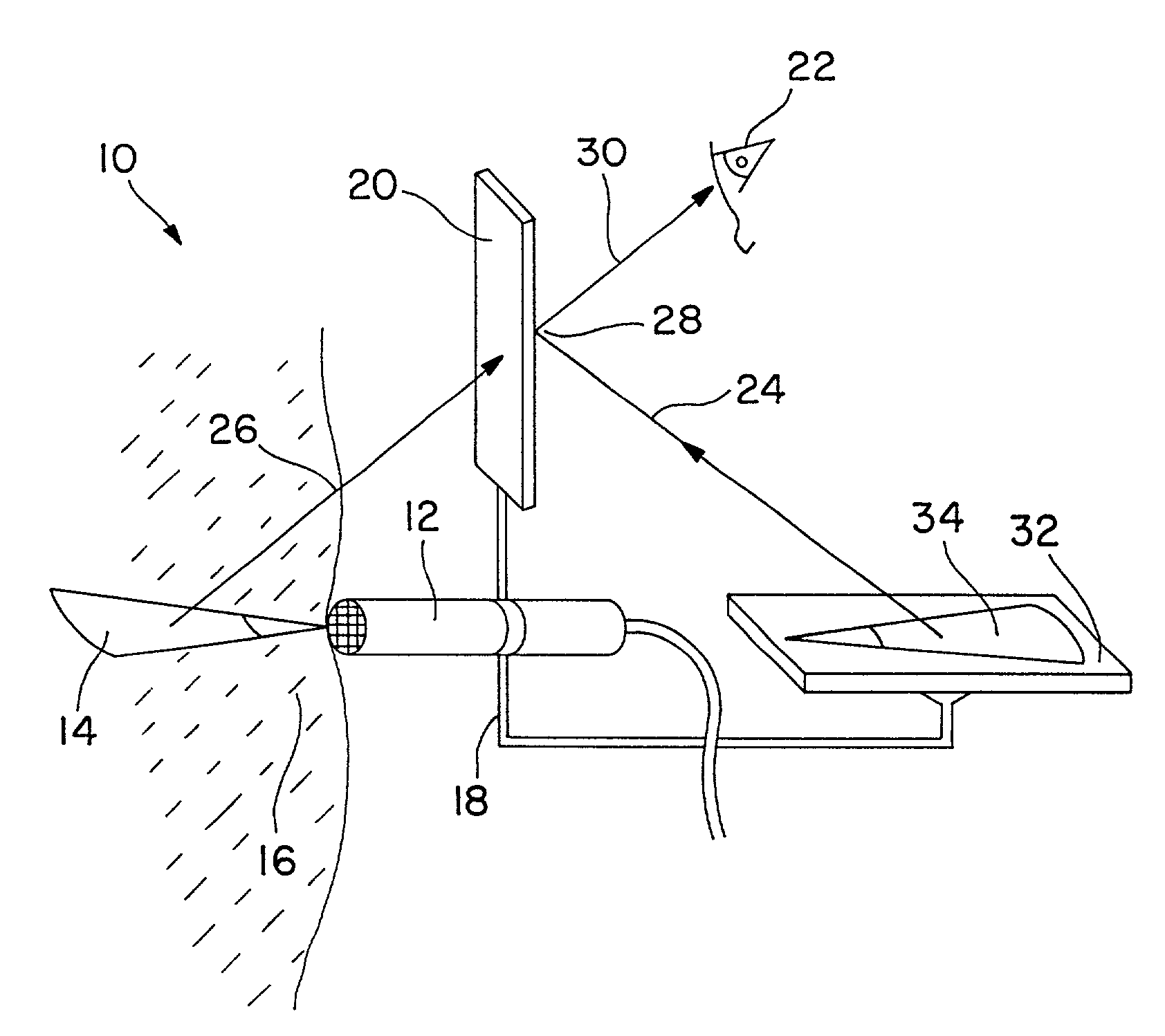
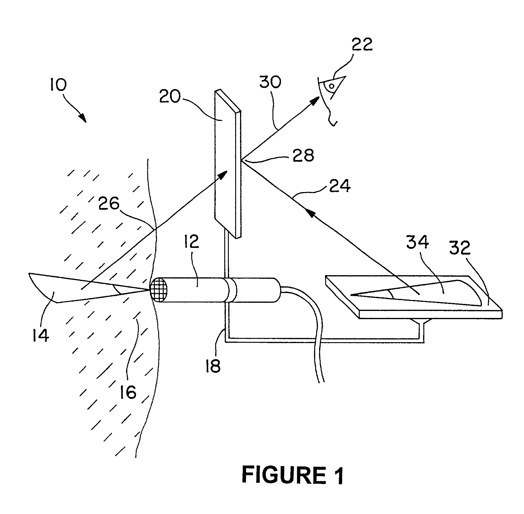
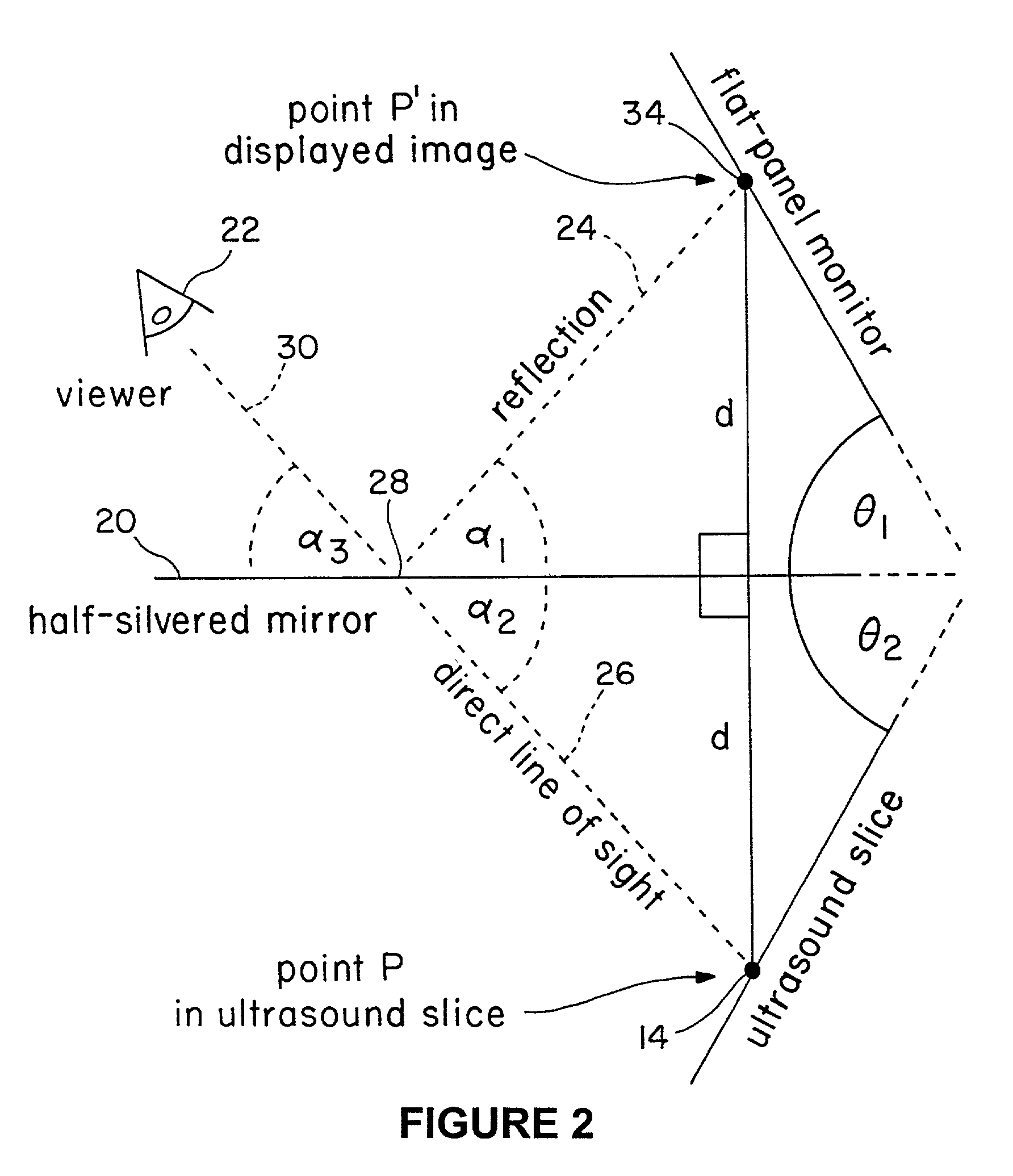
[0034]The invention contemplates, in at least one presently preferred embodiment, a method and device for merging or superimposing the reflection of a two dimensional tomographic image of the interior of a target object with the normal human vision view of the outside of that same tar...


PUM


Abstract

A device for combining tomographic images with human vision using a half-silvered mirror to merge the visual outer surface of an object (or a robotic mock effector) with a simultaneous reflection of a tomographic image from the interior of the object. The device maybe used with various types of image modalities including ultrasound, CT, and MRI. The image capture device and the display may or may not be fixed to the semi-transparent mirror. If not fixed, the imaging device may provide a compensation device that adjusts the reflection of the displayed ultrasound on the half-silvered mirror to account for any change in the image capture device orientation or location.

Description

RELATED APPLICATION DATA[0001]This application claims the benefit and is a CIP of application Ser. No. 09 / 686,677, filed Oct. 11, 2000, and claims the benefit of provisional application Ser. No. 60 / 216,860 filed Jul. 7, 2000.BACKGROUND OF THE INVENTION[0002]1. Field of the Invention[0003]The present invention generally relates to image display devices and methods therefor, and, more particularly, the present invention relates to methods and devices for combining a reflection of a tomographic image with human vision during subcutaneous medical procedures.[0004]2. Description of the Background[0005]Because human vision depends at least partially on the detection of reflected visible light, humans cannot “see” into objects through which light does not pass. In other words, humans cannot see into the interior sections of a non-transparent, solid object. Quite often, and in many different technology areas, this sight limitation may impede or hinder the effective completion of a particula...

Claims


Application Information

Patent Timeline
IPC IPC(8): A61B8/00A61B5/055G01R33/32A61B6/03A61B17/34A61B19/00
CPCA61B8/00A61B8/5238A61B17/3403A61B8/587A61B19/52A61B2017/3413A61B2019/5231A61B2019/5293A61B19/5225A61B8/4218A61B90/36A61B2090/373A61B2090/366A61B90/37A61B2090/365
Inventor STETTEN, GEORGE DEWITTNOWATZYK, ANDREAS G.
Owner UNIVERSITY OF PITTSBURGH
Why Eureka
Try Eureka