System Including Computed Tomography Device For Image Guided Treatment

a computed tomography and image guided technology, applied in the field of computerized tomography, can solve the problems of affecting the treatment effect of patients,

Inactive Publication Date: 2008-08-28
UNIV OF FLORIDA RES FOUNDATION INC
View PDF15 Cites 74 Cited by
  • Summary
  • Abstract
  • Description
  • Claims
  • Application Information

AI Technical Summary

Problems solved by technology

By considering one or more of such sections, skilled medical diagnosticians may diagnose various body elements such as tumors, blood clots, cysts, hemorrhages and various abnormalities, which, heretofore, were detectable, if at all, only by much more cumbersome and, in many instances, more hazardous techniques to the patient.
While systems of the aforementioned type have represented powerful diagnostic tools, and were deemed great advances in the radiography art, first generation systems suffered from many shortcomings.
Acquisition of the raw data frequently entailed an undesirably long period, which, among other things, subjected a patient to both inconvenience and stress.
The patient's inability to remain rigid for such a lengthy period, also led to blurring of the image sought to be obtained.
This complicates treatment, because the healthy tissue and organs must be taken into account when delivering a dose of radiation to the tumor.
These solid jaw blocks, however, do not provide sufficient variability in the field shape.
This can be particularly difficult where the treatment beam is an X-ray beam.
It is also difficult to adjust the field shape where the treatment beam is an electron beam due to electron attenuation and scattering.
The limited number of energies available is a continuing problem for physicians and physicists, since it is not always possible -for them to give the most efficacious treatments.
Such machines, however, will still preclude much other intermediate energy that may be useful.
Nevertheless, these radiation technologies do not permit the system to be able to perform simultaneous treatment of an area using different types of radiation treatments.
Additionally, none of these systems and methods permit computerized tomography to occur during treatment, thereby leading to more accurate treatment of the patient.

Method used


Image

  • System Including Computed Tomography Device For Image Guided Treatment
  • System Including Computed Tomography Device For Image Guided Treatment
  • System Including Computed Tomography Device For Image Guided Treatment

Examples


Embodiment Construction

[0025]The present invention is more particularly described in the following description and examples that are intended to be illustrative only since numerous modifications and variations therein will be apparent to those skilled in the art. As used in the specification and in the claims, the singular form “a,”“an,” and “the” may include plural referents unless the context clearly dictates otherwise. Also, as used in the specification and in the claims, the term “comprising” may include the embodiments “consisting of” and “consisting essentially of.”

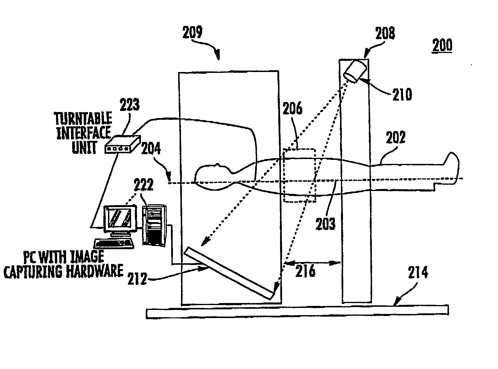
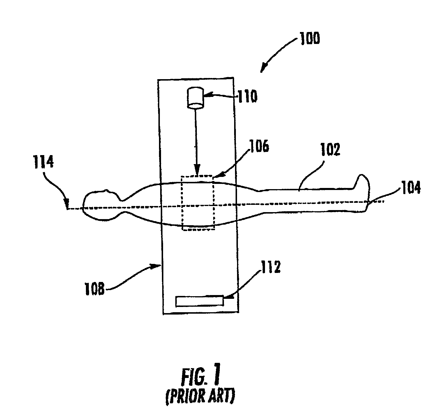
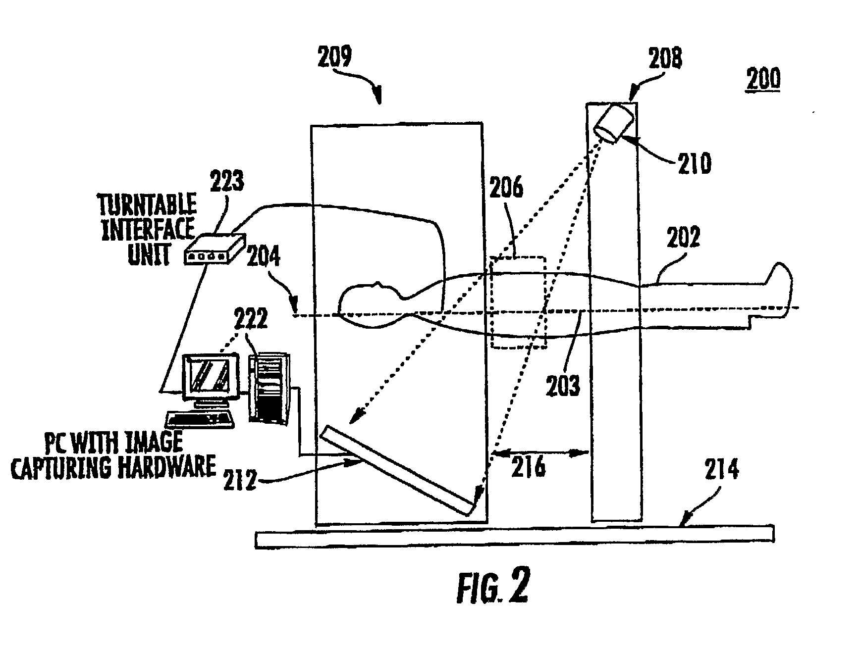
[0026]In general, a CT scan is an x-ray procedure enhanced by a computer. This results in a three-dimensional view (referred to as a “slice”) of a particular part of a patient's body. During a routine x-ray, dense tissues can block other areas. Aided by a computer, a CT scan is able to put together the different “slices” and create a three-dimensional view, clearly showing both bone and soft tissue. Prior art systems performed this system...


PUM


Abstract

A computed tomography (CT) system (300) includes a table (304) for holding a patient (302), a first gantry (311) for holding a radiation source (310) which emits penetrating radiation, and a second gantry (313) spaced apart from the first gantry holding a penetrating radiation detector (312) for receiving the penetrating radiation after passing through the patient. The penetrating radiation from the radiation source is angled at a non-perpendicular angle with respect to a longitudinal axis (322) of the table. A third gantry (320) is spaced apart from the first and second gantry including at least one radiation therapy source (321) or other (non-CT) imaging system, wherein the third gantry is located between the first gantry and the second gantry. The CT system thus permits computed tomography to occur simultaneously or substantially simultaneously with other procedures, such as various other radiation therapy systems, imaging modality or surgical procedures.

Description

FIELD OF THE INVENTION[0001]The present invention relates to computerized tomography. More specifically, the present invention relates to computerized tomography devices that permit computerized tomography to be performed substantially simultaneously with other radiation and / or surgical procedures.BACKGROUND OF THE INVENTION[0002]In recent years, much interest has been evidenced in a field now widely known as computed tomography. In a typical procedure utilizing computed tomography (or CT), an X-ray source and detector are physically coupled together on opposite sides of the portion of a sample which is to be examined. The sample may be, for example, a patient or phantom or other objects. X-rays are made to transit through the sample to be examined, while the detector measures the X-rays which make it through the sample without being absorbed or deflected. Periodically, the paired source and detector are rotated to differing angular orientations about the sample, and the data collec...

Claims


Application Information

Patent Timeline
Patent Type & Authority Applications(United States)
IPC IPC(8): A61B6/00G01T1/164G01T1/166
CPCA61B6/4447A61N2005/1061A61N5/1049
Inventor KIM, SIYONG
Owner UNIV OF FLORIDA RES FOUNDATION INC
Why Eureka
Try Eureka