Cleaning wipe and method of manufacture

a technology of cleaning wipes and fiber webs, applied in carpet cleaners, weaving, cleaning equipments, etc., can solve the problems of sand, food crumbs, residue on the contact surface, and inability to readily remove larger and/or heavier debris

Active Publication Date: 2009-07-14
3M INNOVATIVE PROPERTIES CO
View PDF11 Cites 52 Cited by
  • Summary
  • Abstract
  • Description
  • Claims
  • Application Information

AI Technical Summary

Benefits of technology

[0031]An additional benefit provided by the cleaning wipe 10 of the present invention relates to an ability to retain not only large and / or heavy particles, but also to retain a large volume of any sized particle. With reference to FIG. 4A, for example, a schematic, cross-section of the cleaning wipe 10 is shown following a cleaning operation (it again being recalled that the outer surfaces 14, 16 are shown in FIG. 4A as being substantially flat for ease of illustration). With the one exemplary embodiment of FIG. 4A, the fiber web 12 provides an open structure (i.e., relatively large spacing between individual fibers 22). With this one exemplary construction, relatively large particles 60 (shown schematically in FIG. 4A) can “nest” between individual fibers 22, as can other, smaller-sized debris (not shown). With the representation of FIG. 4A, the outer surface 14 was used as the working surface, and wiped over a surface to be cleaned (not shown). During the cleaning movement, the particles 60 are interjected between the fibers 22, with the tacky material coating causing the so-contacted particles 60 to partially adhere to one or more of the fibers 22 (as do other, smaller particles). Because the tacky material coating level at the outer surface 14 is greatly reduced as compared to that more proximate to the center 24, the particle 60 will not accumulate along the outer surface 14. Instead, the particle 60 is readily deposited within a thickness of the cleaning wipe 10. Thus, the outer or working surface 14 does not become “clogged” with particles, resulting in an increased number or volume of particles collected by the cleaning wipe 10. The close-up, cross-sectional photograph of FIG. 4B further shows the particles 60 (referenced generally in FIG. 4B) being retained within a thickness of one exemplary embodiment of the cleaning wipe 10.

Problems solved by technology

While these and similar cloth materials are quite useful for removing dust and other minute particles from surfaces, they cannot readily remove larger and / or heavier debris (e.g., sand, food crumbs, etc.) because these particles will not adhere to, or be retained by, the cloth.
Treated dust cloths leave a residue on the contacted surface that, while desirable for certain uses (e.g., furniture polishing), is unwanted for most household cleaning activities (e.g., cleaning a counter or floor surface).
Further, when used for general cleaning purposes, treated cloths quickly become saturated with particles at their outer surface, thereby limiting use to short cleaning operations and requiring frequent cleaning of the wipe itself (i.e., removing accumulated particles).
Again, however, these dry wipes are often unable to consistently retain relatively large and / or heavy particles over extended periods of use.
That is to say, relatively large and / or relatively heavy particles do not readily adhere to the dry, electrostatic-type wipes and other dry wipes.
Further, the surface of these products quickly becomes “clogged” with particles, such that the collected debris must be repeatedly removed from the wipe's surface.
This coating, in turn, imparts an adhesive or sticky “feel” to the wipe, and creates significant drag as the tack wipe is moved along the surface being cleaned.
Although such tack wipes have been used in the automotive painting / repainting and wood finishing industries, the negative attributes of available tack wipes have hindered their viability for certain commercial or residential uses (e.g., household or general industrial cleaning).
In any event, the outer surfaces of the resultant tack cloth contain the highest concentration of the PSA, leading to the problems of drag described above.
In such constructions, if the polymeric additive level is too high, the cleaning sheet will not glide easily across the surface being cleaned and / or may tend to leave residue on the surface.
As a result, even though the reduction in adhesive level and zoned distribution may improve handling, the same issues described above will likely remain and others may be raised.
That is to say, the zones at which the polymeric additive is applied may still “feel” sticky, and may create an unacceptable level of drag when the cleaning wipe is moved along a surface.
Further, by reducing the level and location (i.e., provided along less than an entirety of the cleaning wipe outer surface) of the polymeric additive, the resultant cleaning wipe may be less capable of retaining sufficient amounts of particles.
Also, because the polymeric additive is applied to the surface of the base web, even where the web has a relatively open construction, the cleaning wipe surface will again become clogged with particles relatively quickly.
The ability to collect large amounts of relatively sizable and / or heavy particles has not yet been fully satisfied with a product acceptable to most users.

Method used


Image

  • Cleaning wipe and method of manufacture
  • Cleaning wipe and method of manufacture
  • Cleaning wipe and method of manufacture

Examples


example 1

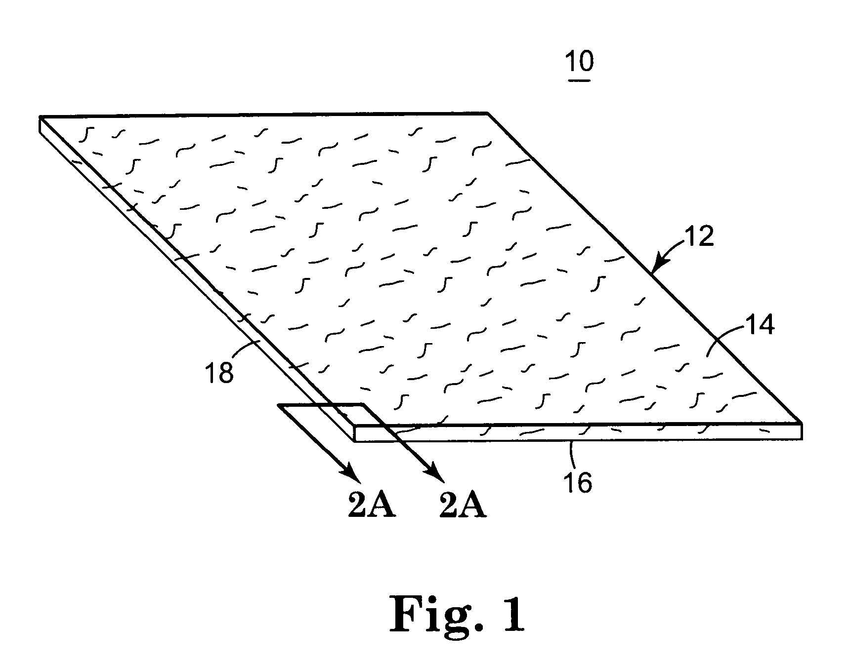
[0061]An airlaid nonwoven web was prepared from 32 denier polyester staple fibers and 12 denier bicomponent melty fibers using a Rando-Webber airlaid machine (Model 12-BS, available from Curlator Corp., East Rochester, N.Y.). The weight ratio of the 32-denier fibers to the 12 denier fibers was approximately 4:1. The basis weight of the web was approximately 40 g / m2.

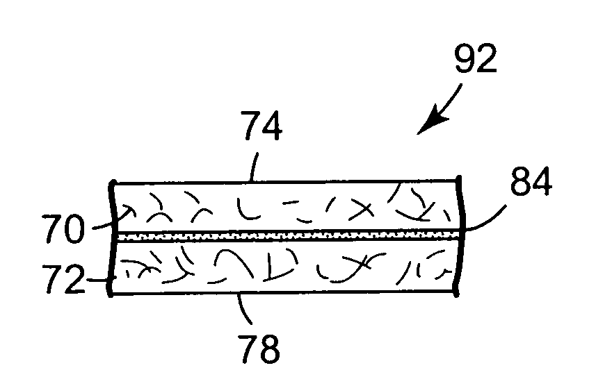
[0062]The web was then transported from the Rando-Webber into a 12-foot long oven using a conveyor belt. The oven had both top and bottom air impingement and was set at a temperature of 350° F. and a line speed of 20 feet per minute, that melted the sheath of the 12 denier bicomponent melty fibers to produce a coherent staple fiber web. The web was then wound into roll form. Two of these webs were then laminated to each other using a hot melt, pressure sensitive adhesive (Type HL-1902, available from H. B. Fuller Company, St. Paul, Minn.). The adhesive was fed using a 4-inch single screw extruder (available from Bonnot Co...

example 2

[0064]An airlaid nonwoven web was prepared from 100 denier polyester staple fibers and 12 denier bicomponent melty fibers using a Rando-Webber airlaid machine (Model 12-BS, available from Curlator Corp., East Rochester, N.Y.). The weight ratio of the 100-denier fibers to the 12-denier fibers was approximately 4:1. The basis weight of the web was approximately 70 g / m2.

[0065]The web was then transported from the Rando-Webber into a 12-foot long oven using a conveyor belt. The oven had both top and bottom air impingement and was set at a temperature of 350° F. and a line speed of 20 feet per minute, that melted the sheath of the 12 denier bicomponent melty fibers to produce a coherent staple fiber web. The web was then wound into roll form. Two of these webs were then laminated to each other using a hot melt, pressure sensitive adhesive (Type H5007-01, available from Bostik Findley, Wauwatosa, Wis.). The adhesive was fed using a 4-inch single screw extruder (available from Bonnot Compa...

example 3

[0067]A carded nonwoven web was prepared from 32 denier polyester staple fibers and 12 denier bicomponent melty fibers using a carding machine (Model M.C., available from Hergeth Hollingsworth, West Germany). The weight ratio of the 32-denier fibers to the 12-denier fibers was approximately 4:1. The basis weight of the web was approximately 65 g / m2.

[0068]The web was then transported from the card machine into a 12-foot long oven using a conveyor belt. The oven had both top and bottom air impingement and was set at a temperature of 350° F. and a line speed of 20 feet per minute, that melted the sheath of the 12 denier bicomponent melty fibers to produce a coherent staple fiber web. The web was then wound into roll form. Two of these webs were then laminated to each other using a hot melt, pressure sensitive adhesive (Type HL-2168, available from H.B. Fuller Company, St. Paul, Minn.). The adhesive was fed using a 4-inch single screw extruder (available from Bonnot Company, Uniontown, ...


PUM

PropertyMeasurementUnit
mean diameteraaaaaaaaaa
diameteraaaaaaaaaa

Abstract

A cleaning wipe including a fiber web and a tacky material. The fiber web defines opposing surfaces and an intermediate region between the opposing surfaces. In this regard, at least one of the opposing surfaces serves as a working surface for the cleaning wipe. The tacky material is applied to the web such that a level of tacky material is greater in the intermediate region than at the working surface. In one embodiment, the amount of tacky material per area of web material is greater in the intermediate region than at either of the opposing surfaces. In another embodiment, the fiber web is a nonwoven fiber web.

Description

FIELD OF THE INVENTION[0001]The present invention relates to a fiber web-based wiping construction. More particularly, it relates to fiber web material cleaning wipe constructions incorporating a tacky material and exhibiting a minimal surface drag characteristic.BACKGROUND OF THE INVENTION[0002]Cleaning wiping products (or wipes or sheets) in various forms have long been used to clean debris from surfaces in residential and commercial environments. Most available cleaning wipe products have the same basic form, including a relatively thin base comprised of a fibrous material (or web) that is at least somewhat supple to enhance user handling. To this end, a number of different materials and manufacturing techniques have been developed (e.g., woven, nonwoven, or knitted base structure comprised of natural and / or synthetic fibers), each having certain characteristics adapted to at least partially satisfy a particular end use. In addition, efforts have been made to incorporate certain ...

Claims


Application Information

Patent Timeline
Patent Type & Authority Patents(United States)
IPC IPC(8): B32B3/00B32B3/02A47L13/16A47L25/00D04H1/559D04H13/00
CPCA47L13/16A47L25/005D04H13/006Y10T156/1015Y10T428/2933Y10T428/2971Y10T428/2913Y10T442/2016Y10T442/20Y10T442/2738A47L25/00D04H13/00
Inventor ZILLIG, DANIEL J.OLSON, GARY L.HASKETT, THOMAS E.
Owner 3M INNOVATIVE PROPERTIES CO
Why Eureka
Try Eureka