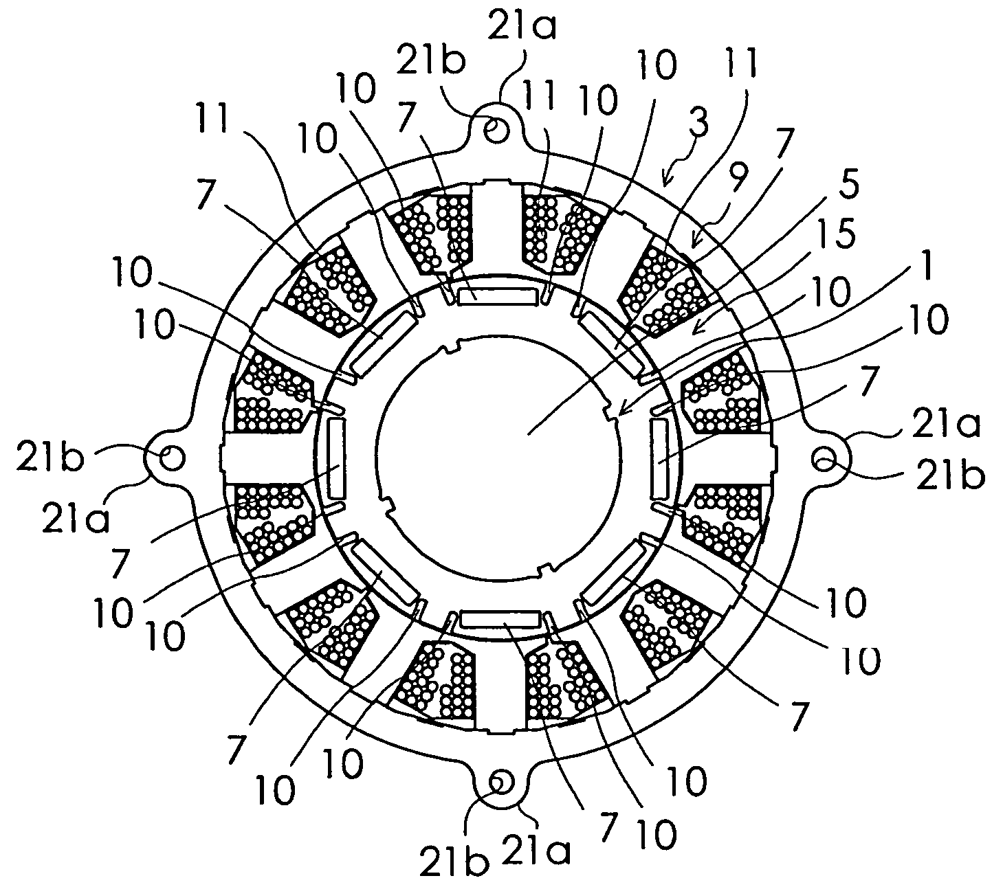
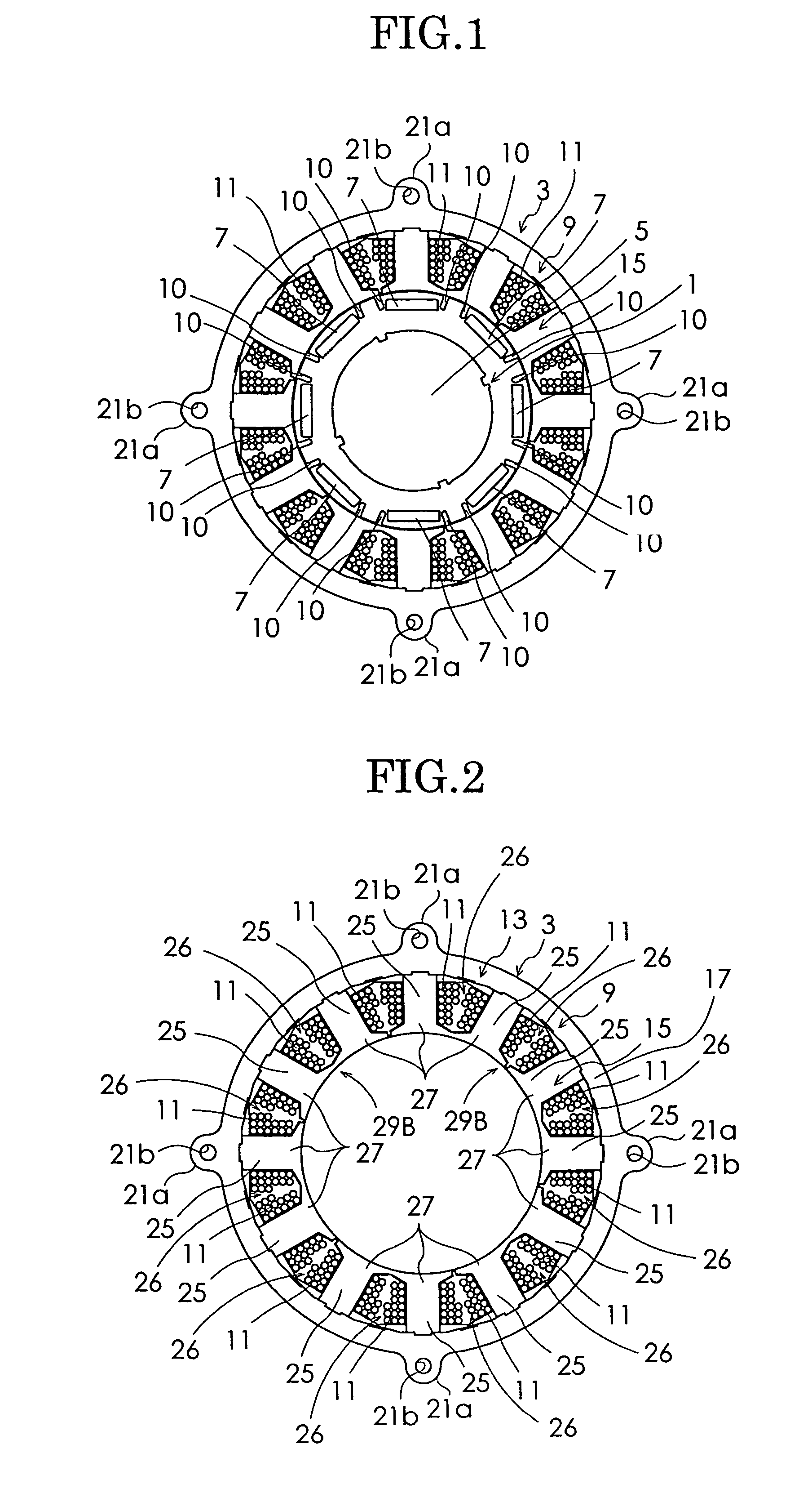
[0009]Magnitudes of cogging torques caused by the first and second types connecting portions may differ and a phase difference between the cogging torques caused by the first and second types connecting portions may be shifted by a half period. For this reason, assume that the first and second types connecting portions are alternately arranged in the circumferential direction and the thicknesses of the first and second types connecting portions in the radial direction are made to be different as in the present invention. Then, by appropriately setting the thickness of the first and second types connecting portions so that the amplitudes of the cogging torques caused by the first and second types connecting portions have the same size and so that the phase difference between the cogging torques is shifted by the half period, the cogging torque of the motor can be uniformly reduced over an entire stator after it has been arranged that the torque is not greatly reduced. In the present invention in particular, sectional shapes of the slots can be made to be the same. Accordingly, the lamination factor of windings can be kept in a certain range. Further, the stator for the rotary motor can be easily manufactured.
[0010]When the number of the permanent magnet magnetic pole portions P and the number of the slots N have a relation of P=4 m and N=6 m (m: a natural number), it is preferable that the thicknesses T1 and T2 has a relation in which a ratio T2 / T1 is in the range of two to three. Generally, in the permanent magnet rotary motor, the number of the amplitudes of the cogging torque per revolution of the rotor is a least common multiple [LCM (P, N)] between the number of the permanent magnet magnetic pole portions P and the number of the slots N. When the numbers P and N have the relation of P=4 m and N=6 m (m: a natural number), the least common multiple [LCM (P, N)] between the numbers P and N is equal to a least common multiple [LCM (P, N / 2)] between the number P and a number N / 2. For this reason, in the motor having the relation of P=4 m and N=6 m (m: a natural number) and a motor having a relation of P=4 m and N=3 m (m: the natural number) with the number of the slots thereof halved, the numbers of the amplitudes of the cogging torques per revolution of the rotor are the same. However, the phases of the cogging torques are different by the half period or 180 degrees. Accordingly, assume that the function of the slots in the motor having the relation of P=4 m and N=6 m (m: a natural number) can be made close to the function of the slots in the motor with the number of the slots thereof halved, which has the relation of P=4 m and N=3 m. Then, due to cancelling out of the cogging torques generated by attracting power between the rotor and the respective stator slots of the motor, the cogging torque of the motor as a whole can be reduced. Accordingly, in the present invention, the thicknesses of the first type connecting portions and the second type connecting portions in the radial direction were made to be different as described above. Then, the cogging torques caused by the first and second types connecting portions that are alternately arranged in the circumferential direction were canceled out. This effect is particularly pronounced when the thicknesses T1 and T2 have the relation that the ratio T2 / T1 is in the range of two to three. In this state, the sectional shapes of the slots can be made to be the same. Accordingly, reduction of interlinkage magnetic flux can be suppressed, and the cogging torque can be thereby reduced.
[0011]When the number of the permanent magnet magnetic pole portions P and the number of the slots N have a relation of P=8 m and N=6 m (m: a natural number), it is preferable that an opening angle θ1 of a part having substantially the identical thickness for each of the first type connecting portions is set to be larger than an opening angle θ2 of a part having substantially the identical thickness for each of the second type connecting portions, and that an opening angle difference θ1−θ2=[360° / LCM(P, N)]×(⅓)±1°. Incidentally, the “opening angle” herein means an angle between two virtual line segments, each of which connects the center of the rotor and each of the both ends of a portion of each connecting portion in the circumferential direction of the annular yoke having substantially the identical thickness. The LCM (P, N) means the least common multiple between the numbers P and N. By satisfying the conditions described above, the cogging torque of the motor can be reduced. When the opening angle difference (θ1−θ2) is below [360° / LCM (P, N)]×(⅓)−1°, the cogging torque will increase, and the interlinkage magnetic flux will be reduced. When the opening angle difference (θ1−θ2) exceeds [360° / LCM (P, N)]×(⅓)+1°, the cogging torque will increase.
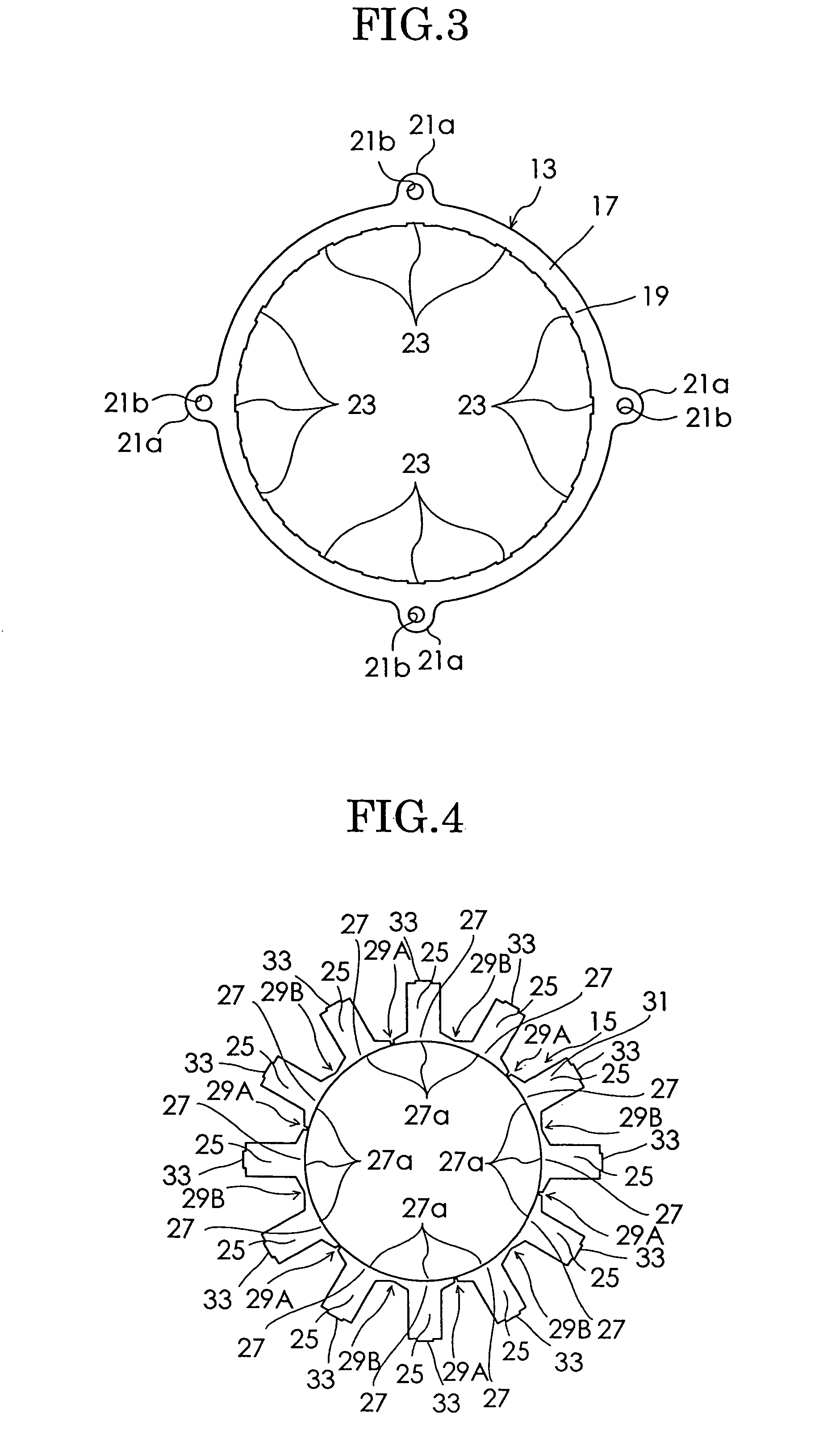
[0013]Preferably, the stator core is formed by a combination of a plurality of divided core units each constituted by lamination of a plurality of electromagnetic steel plates. With this arrangement, the windings can be easily wound around the pole pieces, so that the stator core can be easily manufactured. In this case, the divided core units can be constituted by a first divided core unit constituting the yoke portion and a second divided core unit constituted by the pole pieces, the magnetic pole surface constituent portions, and the connecting portions. The pole pieces, magnetic pole surface constituent portions, and connecting portions are formed integrally with one another. When the divided core units are configured as described above, the stator core can be formed using the following winding methods for the exciting winding portions: in one method, insulators are arranged at the pole pieces of the second divided core unit, and the exciting windings are wound around the insulators. Then, the pole pieces are fixed to the yoke portion by fitting or the like, thereby combining the first divided core unit with the second divided core unit. The stator core can be thereby formed. In another method, the exciting windings are wound around bobbins formed of an insulating material. Then, the bobbins with the exciting windings wound therearound are mounted on the pole pieces of the second divided core unit. The pole pieces are then fixed to the yoke portion by fitting or the like. With this arrangement, the first divided core unit can be combined with the second divided core unit, and the stator core can be thereby formed. When such methods are used, the lamination factor of the exciting windings can be increased. For this reason, by selecting a desired one of the above-mentioned winding methods, the exciting windings can be easily wound around the pole pieces. In addition, in one operation of coupling the pole pieces to the yoke portion, the stator core can be formed.
[0015]The divided core units can also be constituted by a first divided core unit having the yoke portion; a second divided core unit having the magnetic pole constituent portions and the connecting portions that are formed integrally with one another; and third divided core units each constituting each of the pole pieces. With this arrangement, even if the number of components for the permanent magnet rotary motor is increased, the exciting windings can be more easily wound around the pole pieces.
[0016]According to the present invention, when a plurality of the connecting portions are employed for the permanent magnet rotary motor, the torque increases due to the first type connecting portions, while the cogging torque is reduced due to the second connecting portions. Therefore, by appropriately setting the thickness of the first and second types connecting portions in the radial direction of the stator core and the circumferential lengths of the first and second types connecting portions that are alternately arranged in the circumferential direction, the cogging torque can be uniformly reduced over the entire stator after it has been arranged in such a manner that the torque is not greatly reduced. In the present invention in particular, the sectional shapes of the slots can be made to be same. Thus, the lamination factor of the windings can be made to be constant. Further, the permanent magnet rotary motor can be easily manufactured.


