Apparatus and method for eddy-current scanning of a surface to detect cracks and other defects

a technology of eddy-current scanning and surface, applied in the field of non-destructive eddy-current testing, can solve the problems of affecting the magnetic field, causing changes to the observed rfec or conventional ec signal, etc., and achieves substantial flexibility in controlling parameters and avoiding mechanical noise

Active Publication Date: 2009-07-14
INNOVATIVE MATERIALS TESTING TECH
View PDF71 Cites 106 Cited by
  • Summary
  • Abstract
  • Description
  • Claims
  • Application Information

AI Technical Summary

Benefits of technology

[0010]In some embodiments, the invention provides an apparatus that includes a plurality of coils (e.g., numerous thin-film coils formed in an array on a flex circuit), each of the coils acting as an excitation unit that generates an alternating excitation magnetic signal; and as a sensor that is configured to detect eddy-current-signal phase and amplitude changes (due to anomalies in the surface being inspected) relative to the excitation magnetic signal. In some embodiments, the apparatus is configured to electronically scan a surface (e.g., of a metal plate) by successively switching to individual ones of the plurality of excitation / sensing coils (using, e.g., an analog multiplexer or switch) without physical movement of the apparatus in order to detect anomalous signal changes in a manner that reduces signal changes due to probe lift-off between the probe and the surface.
[0015]In some embodiments, the working principle of a magnetic carpet probe (MCP) according to the present invention is the same as for a conventional eddy-current probe working in differential mode. In some embodiments of the present invention, one coil is used to electromagnetically sense the object and the other coil acts as a reference to which to compare the sensed signal. In some embodiments, the differences between the present invention and a conventional eddy-current probe include: (a.) the two-dimensional (2D)—coil array of the test unit that allows a quick and static electronic scan (i.e., a scan done without moving the sensor array relative to the section of the object being scanned), which eliminates mechanical “noise” (signal changes due to variations in distance between the coils and the object being sensed); (b.) coils are formed in a piece of flex circuit that can conform to a surface of complex geometry; and (c.) there is substantial flexibility in controlling parameters of the scan and data display using a programmable device.

Problems solved by technology

Cracks, discontinuities, holes, and changes in the material content all affect the eddy-current flow within an object and also affect the magnetic field external to the object.
Changes to an observed RFEC or conventional EC signal can be caused by undesirable anomalies, even those hidden in a surface, such as cracks, voids, internal or surface corrosion, embedded foreign objects, alloy-composition changes, etc., as well as by expected inherent features of the object being examined, such as joints and fasteners.

Method used


Image

  • Apparatus and method for eddy-current scanning of a surface to detect cracks and other defects
  • Apparatus and method for eddy-current scanning of a surface to detect cracks and other defects
  • Apparatus and method for eddy-current scanning of a surface to detect cracks and other defects

Examples


Embodiment Construction

[0034]In the following detailed description of the preferred embodiments, reference is made to the accompanying drawings that form a part hereof, and in which are shown by way of illustration specific embodiments in which the invention may be practiced. It is to be understood that other embodiments may be utilized and structural changes may be made without departing from the scope of the present invention.

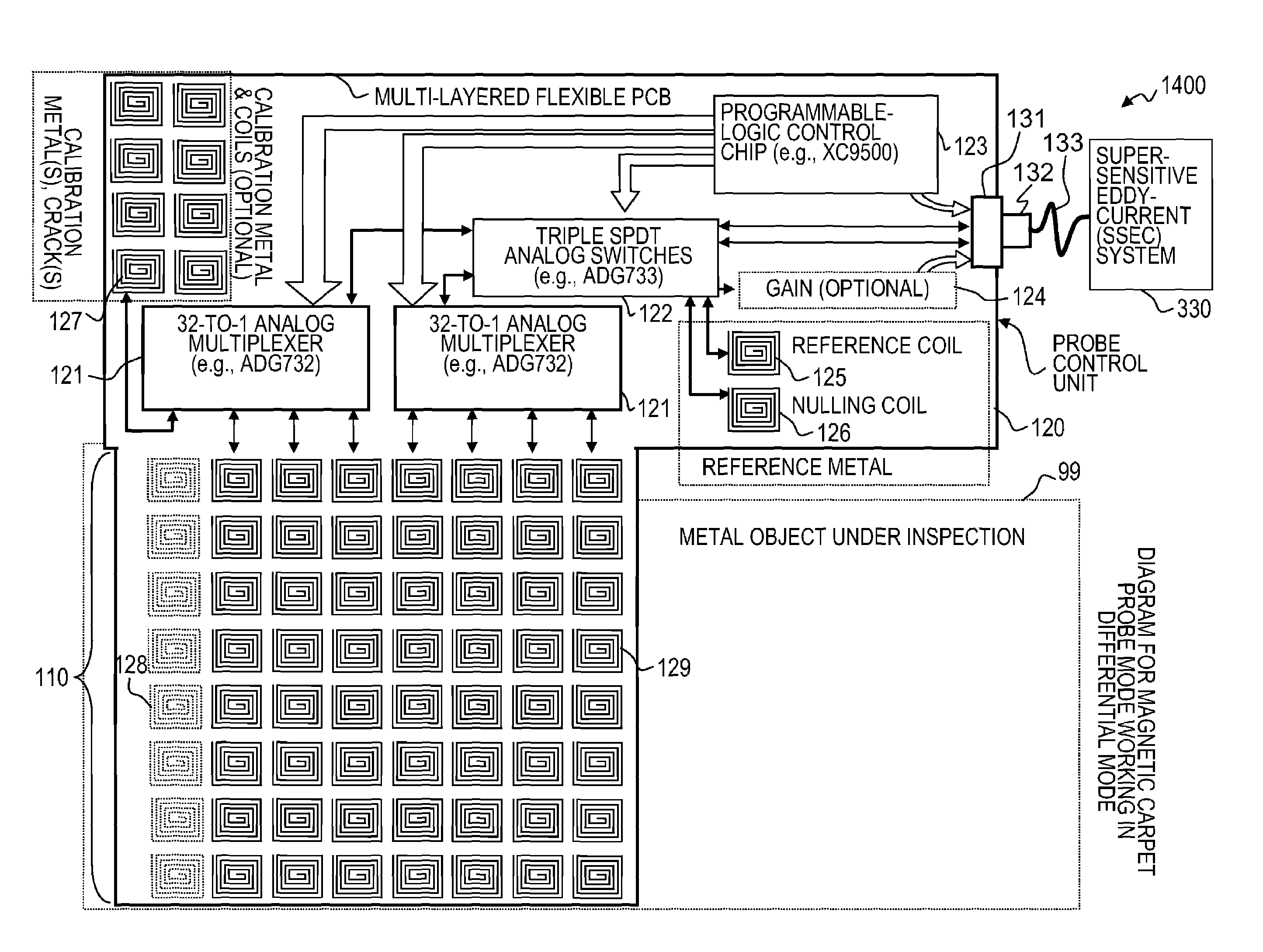
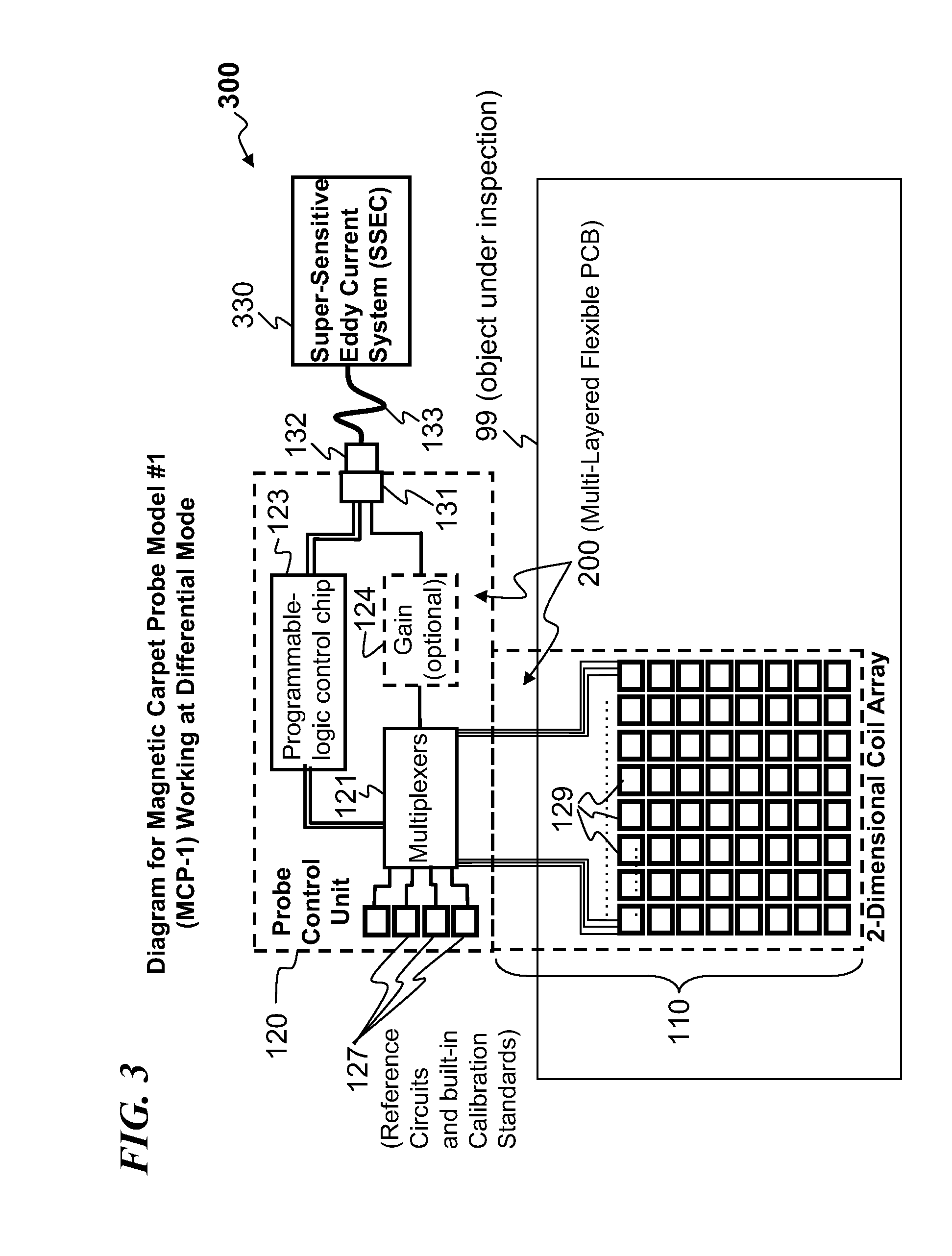
[0035]The invention provides methods and apparatuses that can be used to scan an object for an anomaly. Generally, an apparatus of the invention is placed onto a surface of the object to be scanned so that an excitation-sensing unit that is a part of the apparatus is positioned to force an alternating excitation magnetic field into the object. The magnetic field produces conventional eddy currents that can be detected in close proximity to the excitation unit.

[0036]The amplitude and phase of the eddy-current of an excitation-sensing coil will stay substantially equal to the amplitu...


PUM

PropertyMeasurementUnit
impedanceaaaaaaaaaa
magneticaaaaaaaaaa
period of timeaaaaaaaaaa

Abstract

An apparatus having a plurality of coils (e.g., numerous thin-film coils formed in an array on a flex circuit), each coil acting as an excitation unit that generates an alternating excitation magnetic signal; and as a sensor configured to detect an eddy-current signal's phase and amplitude changes relative to the excitation magnetic signal. In some embodiments, the apparatus electronically scans a surface (e.g., of a metal plate) by successively switching to individual ones of the plurality of excitation / sensing coils (using, e.g., an analog multiplexer) without physical movement in order to detect anomalous signal changes in a manner that reduces signal changes due to probe lift-off relative to the surface. In some embodiments, the coils are placed across a large area of interest, for inspection of a large surface area in a few seconds without moving the apparatus. This can provide high-sensitivity detection and an accurate indication of flaw locations.

Description

REFERENCE TO RELATED APPLICATIONS[0001]This application claims benefit of U.S. Provisional Patent Application Ser. No. 60 / 731,321, filed on Oct. 28, 2005 and titled “APPARATUS AND METHOD FOR EDDY-CURRENT SCANNING OF A SURFACE TO DETECT CRACKS AND OTHER DEFECTS,” which is incorporated herein by reference in its entirety. This application is also related to U.S. patent application Ser. No. 11 / 114,507, filed Apr. 25, 2005 and titled “APPARATUS AND METHOD FOR EDDY-CURRENT MAGNETIC SCANNING A SURFACE TO DETECT SUB-SURFACE CRACKS AROUND A BOUNDARY,” which is incorporated herein by reference in its entirety.STATEMENT REGARDING FEDERALLY SPONSORED RESEARCH OR DEVELOPMENT[0002]This invention was made with Government support under Contract No. DTFACT-04-00013 awarded by the Federal Aviation Administration (FAA). The Government has certain rights in the invention.FIELD OF THE INVENTION[0003]The present invention relates to non-destructive eddy-current testing, and more particularly, to electro...

Claims


Application Information

Patent Timeline
Patent Type & Authority Patents(United States)
IPC IPC(8): G01N27/90G01R33/12
CPCG01N27/902G01R33/10G01R33/04G01R33/028
Inventor OUYANG, TIANHESUN, YUSHI
Owner INNOVATIVE MATERIALS TESTING TECH
Why Eureka
Try Eureka