
Anti-tamper electronic obscurity using E-fuse technology

a technology of electronic obscurity and e-fuse, applied in the field of electronic circuits, can solve problems such as circuit elements not operating normally

Inactive Publication Date: 2009-07-14
IBM CORP
View PDF3 Cites 8 Cited by
  • Summary
  • Abstract
  • Description
  • Claims
  • Application Information

AI Technical Summary

Benefits of technology

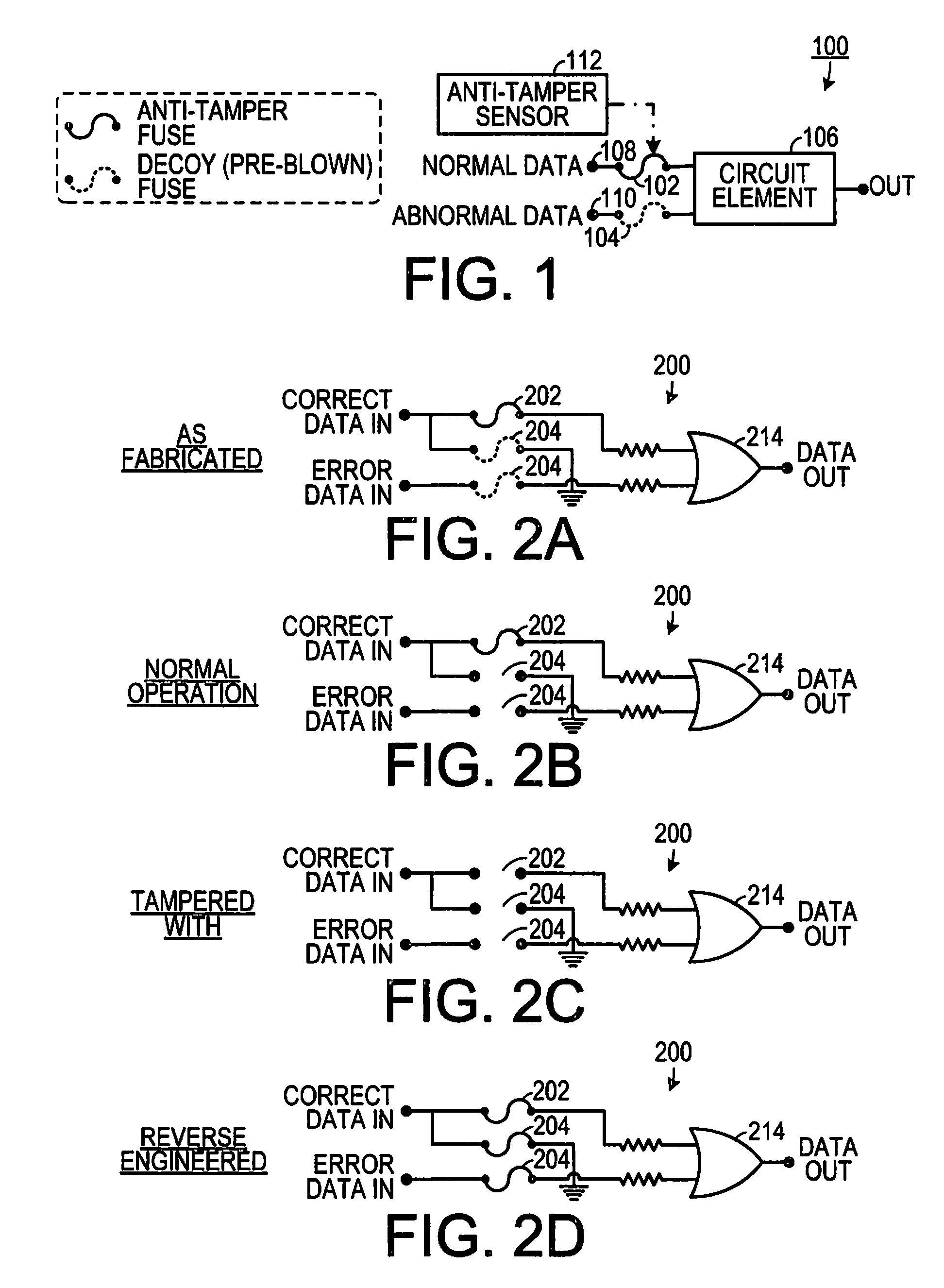
[0012]In yet another aspect, the invention is a method of preventing tampering with and reverse engineering of a circuit that is equipped with an anti-tamper sensor at least one anti-tamper fuse is coupled into a first selected circuit path so that the circuit will operate normally if the fuse is intact and so that the circuit will not operate normally if the fuse is blown. The anti-tamper fuse is responsive to the anti-tamper sensor so that the anti-tamper fuse blows when the anti-tamper sensor detects a tamper condition. At least one decoy fuse is coupled into a second selected circuit path so that the circuit will operate normally if the decoy fuse is blown and so that the circuit will not operate normally if the decoy fuse is intact. The decoy fuse is blown prior to initial operation of the circuit.

Problems solved by technology

However, the decoy coupling element will cause the circuit element not to operate normally if the decoy coupling element has a selected physical property of the selective coupling element in the first state.

Method used


Image

  • Anti-tamper electronic obscurity using E-fuse technology
  • Anti-tamper electronic obscurity using E-fuse technology
  • Anti-tamper electronic obscurity using E-fuse technology

Examples


Embodiment Construction

[0017]A preferred embodiment of the invention is now described in detail. Referring to the drawings, like numbers indicate like parts throughout the views. As used in the description herein and throughout the claims, the following terms take the meanings explicitly associated herein, unless the context clearly dictates otherwise: the meaning of “a,”“an,” and “the” includes plural reference, the meaning of “in” includes “in” and “on.”

[0018]As shown in FIG. 1, one embodiment is a circuit 100 that includes a circuit element 106 that is responsive to a first input 108 and to a second input 110. A selective coupling element 102, such as a fuse, couples the circuit element 106 to the first input 108. The first selective coupling element 102 is responsive to an anti-tamper sensor 112 and has a first state (e.g., not blown, in the fuse example shown) that allows the circuit element to operate normally when the anti-tamper sensor does not detect a tamper condition. The first selective coupli...


PUM


Abstract

A circuit that employs an anti-tamper sensor includes a circuit element that is responsive to a first input and to a second input. A selective coupling element couples the circuit element to the first input and is responsive to the anti-tamper sensor. The selective coupling element has a first state that allows the circuit element to operate normally when the anti-tamper sensor does not detect a tamper condition and is configured to enter a second state that causes the circuit element to become inoperable when the anti-tamper sensor detects a tamper condition. A decoy coupling element is disposed between the second input and the circuit element and has an appearance corresponding to the selective coupling element. The decoy coupling element will cause the circuit element not to operate normally if the decoy coupling element has a selected physical property of the selective coupling element in the first state.

Description

BACKGROUND OF THE INVENTION[0001]1. Field of the Invention[0002]The present invention relates to electronic circuits and, more specifically, to an electronic circuit that increases the difficulty associated with reverse engineering.[0003]2. Description of the Prior Art[0004]Reverse engineering is a common way for someone to misappropriate technology, such as electronic circuits. Typically, the reverse engineer disassembles an apparatus to determine how its component parts interact. In the case of application specific integrated circuits (ASICs), a reverse engineer may cut off successive layers of a circuit package and image them to determine the placement of the various circuit components that make up the ASIC.[0005]One way to guard against reverse engineering is to include a plurality of anti-tamper fuses in critical data paths of a circuit. The fuses are coupled to a tampering detection device that causes the fuses to blow when the circuit is being tampered with. Since the fuses a...

Claims


Application Information

Patent Timeline
Patent Type & Authority Patents(United States)
IPC IPC(8): G08B21/00
CPCG06F21/75G06K19/07372G06F21/86G06F2221/2123
Inventor DILUOFFO, VINCENT V.EBERHARD, RAYMOND J.
Owner IBM CORP
Learn More