
Method and apparatus for wirelessly controlling devices peripheral to AV device

a technology of wireless control and peripherals, applied in lighting and heating apparatus, television systems, instruments, etc., can solve the problems of inconvenient individual setting of the operation of each av device, inconvenient individual setting of the work of setting devices, and inability to ensure the correct operation of the setting

Inactive Publication Date: 2009-07-14
SAMSUNG ELECTRONICS CO LTD
View PDF8 Cites 30 Cited by
  • Summary
  • Abstract
  • Description
  • Claims
  • Application Information

AI Technical Summary

Benefits of technology

Enables seamless, automated control of AV devices with a single remote control, reducing user inconvenience and installation limitations, allowing flexible placement of the host device and simultaneous AV signal reception and control.

Problems solved by technology

The conventional methods have the following problems.
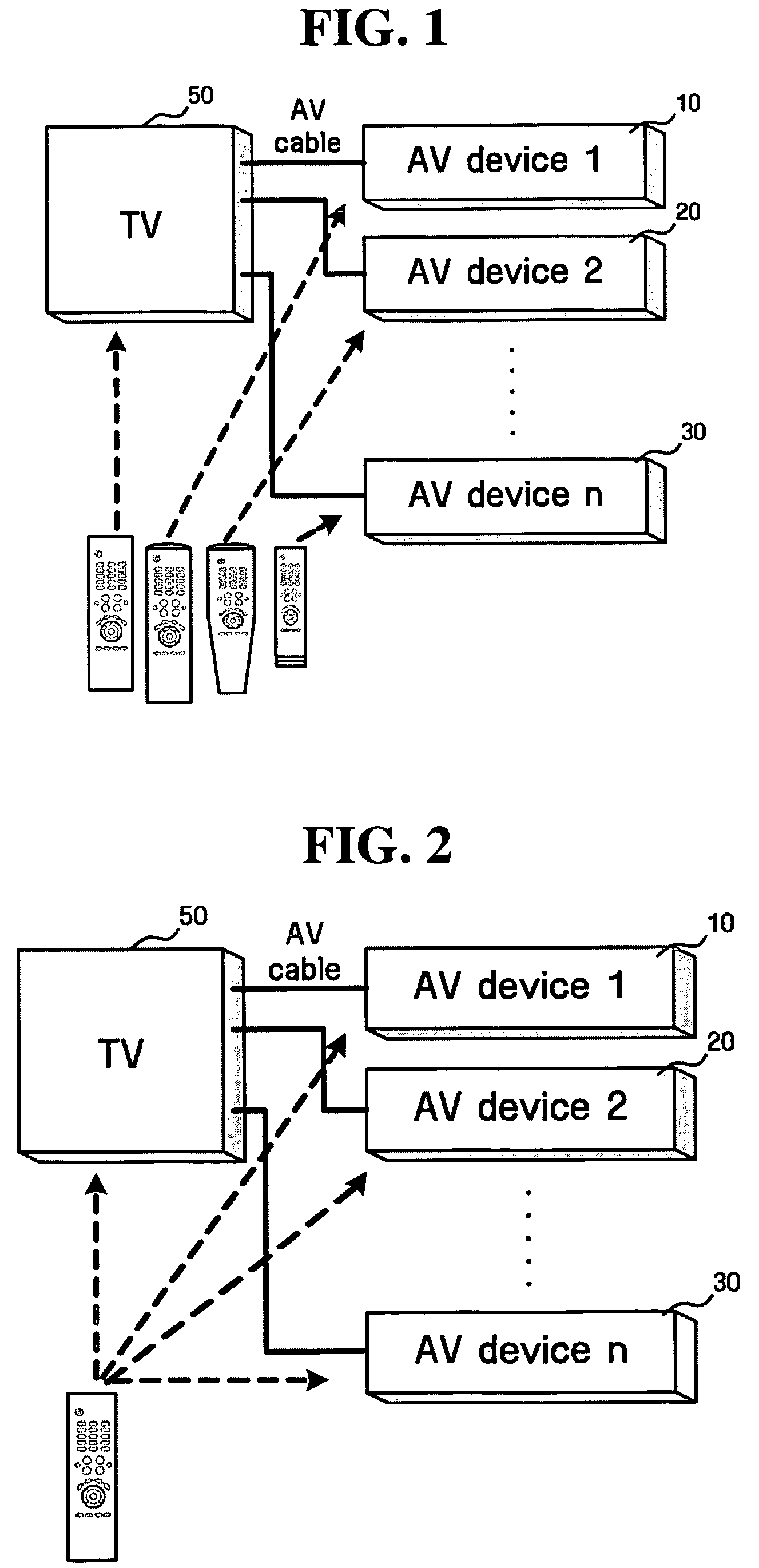
First, it is inconvenient for a user to individually set the operation of each AV device by using a corresponding remote control in order to set a series of operations.
Secondly, it is inconvenient for a user to individually perform the work of setting devices by means of a corresponding remote control (by switching to a corresponding mode of an integrated remote control) whenever the user changes a setting for another operation.
Thirdly, since a basic knowledge about each device is necessary in setting each AV device, there is no guarantee that a setting is correctly performed when an automatic setting is performed by means of a macro function because the AV device may be incorrectly connected to a TV.
Fourthly, since the TV and the AV devices are connected to each other through wired AV cables, it is difficult to dispose the TV at random locations or locations far from the AV devices.
That is, there is a limitation in that the TV must be installed at locations where the AV cables can reach.

Method used


Image

  • Method and apparatus for wirelessly controlling devices peripheral to AV device
  • Method and apparatus for wirelessly controlling devices peripheral to AV device
  • Method and apparatus for wirelessly controlling devices peripheral to AV device

Examples


first embodiment

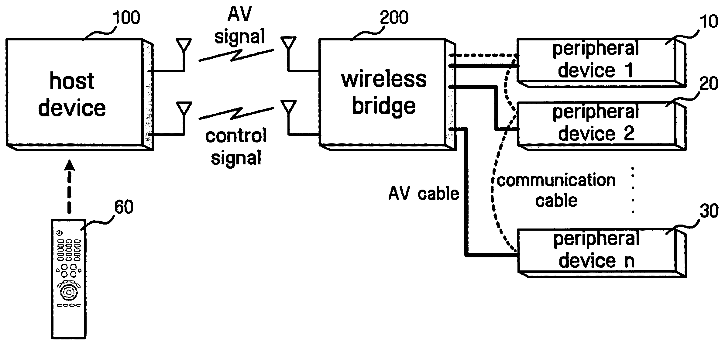
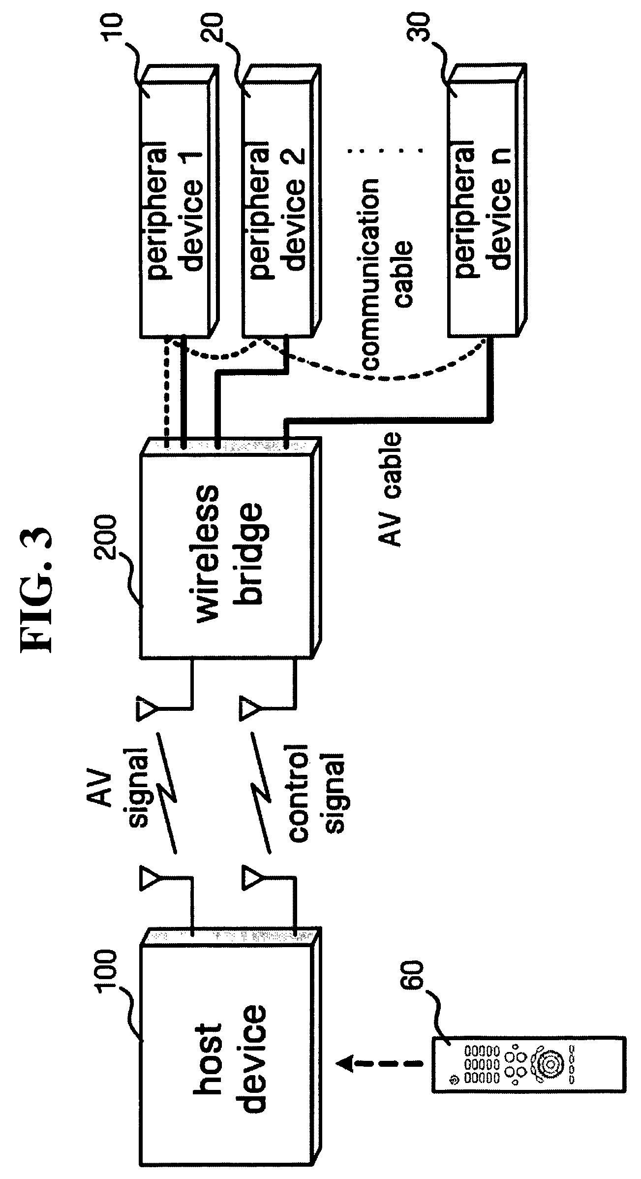
[0052]FIGS. 4A and 4B are block diagrams showing constructions of the host device 100 and the wireless bridge 200 according to the present invention. The host device 100 may include a control unit 110, a wireless transceiver 120, a remote control input unit 130, a memory unit 140, an ID allocation unit 150, a control signal generation unit 160, an overlay unit 170 and an AV output unit 180. The wireless transceiver 120 may include an AV signal receiving unit 121, a control signal transceiver 122 and a decoding unit 123.

[0053]Herein, the control signal transceiver 122 transmits a control signal generated by the control signal generation unit 160 and receives a control signal from the wireless bridge 200. The AV signal reception unit 121 receives an AV signal from the wireless bridge 200 and the decoding unit 123 decodes the AV signal to restore a video and audio.

[0054]The remote control input unit 130 receives a key code value inputted by a user. Further, the memory unit 140 stores d...

second embodiment

[0139]First, a detailed operation will be described with reference to FIG. 20. This case is a case in which both the host device 100 and the wireless bridge 200 have OSD bitmaps stored in the memory units 140 and 240 and have an ability of independently displaying OSDs. When a user presses the automation menu button of the remote control, the host device 100 transmits a remote control key code corresponding to the automation menu button to the wireless bridge 200 through the control signal transceiver 122.

[0140]The wireless bridge 200 overlays a OSD menu bitmap stored in the memory unit 240 therein on an AV signal through the overlay unit 280, sends the overlaid OSD menu bitmap to a monitor output and simultaneously sends an ACK signal to the host device 100 through the control signal transceiver 122. The host device 100 having received the ACK signal also overlays a OSD menu on the AV signal and displays the OSD menu on a screen.

[0141]When the user presses the direction key button...

third embodiment

[0156]In the descriptions of the first to the third embodiment, an interface between the host device 100 and a user is accomplished through the OSD menu as shown in FIG. 18, but the scope of the present invention is not limited to the OSD menu. That is, a remote control key code is allocated to each item of the OSD menu and only one remote control key is pressed, so that the peripheral devices 300 can simply perform a series of operations.

[0157]Meanwhile, as described above, in order to perform a control automation of the peripheral devices 300, the host device 100 or the wireless bridge 200 must assign IDs to the peripheral devices 300 currently connected through the device recognition and ID assignment process, the host device 100 must send a control signal for finding out connection states between the wireless bridge 200 and the peripheral devices 300, the host device 100 must receive a response signal for the control signal, and the host device 100 must store information on the ...


PUM


Abstract

Apparatus and method which integrates and automates AV system to control peripheral devices with one remote control including wireless bridge connected to peripheral devices through a network and a host device which receives a remote control input of a user, transmits a control signal to wireless bridge wirelessly, receives a video and an audio from the wireless bridge wirelessly, and displays received video and audio to user. A video device includes a wireless bridge transmitting a control signal for controlling a peripheral device to the peripheral device through a communication cable, receiving a response signal for the control signal from the peripheral device and receiving an AV signal from the peripheral device through an AV cable according to the control signal, and a host device for wirelessly receiving the inputted AV signal from the wireless bridge and displaying a video or an audio restored from the AV signal to user.

Description

CROSS-REFERENCE TO RELATED APPLICATION[0001]This application claims the priority of Korean Patent Application No. 10-2004-0000733 filed on Jan. 6, 2004, in the Korean Intellectual Property Office, the disclosure of which is incorporated herein in its entirety by reference.BACKGROUND OF THE INVENTION[0002]1. Field of the Invention[0003]The present invention relates to a method for controlling a plurality of peripheral devices with one remote control, and more particularly, to an apparatus and method which integrates and automates an AV system so as to control a plurality of peripheral devices with one remote control in the AV system including a wireless bridge connected to the peripheral devices through communication cables in a network and a host device which receives a remote control input of a user, transmits a control signal to the wireless bridge wirelessly, receives a video and audio from the wireless bridge wirelessly, and displays the received video and audio to the user.[000...

Claims


Application Information

Patent Timeline
Patent Type & Authority Patents(United States)
IPC IPC(8): H04N5/44H04N7/16H03J9/00H04N5/38H04Q9/00H04N5/445H04N7/24
CPCH04N5/44513H04N21/44227H04N21/485H04N21/4108H04N21/42204H04N21/43637H04N21/43632G08C2201/40G08C2201/41H03J9/00H04N5/38H04N21/47F21S4/26F21K9/69F21Y2115/10G09F2013/222
Inventor KIM, JAE-KWONKIM, HYO-DAEPARK, JONG-WOOK
Owner SAMSUNG ELECTRONICS CO LTD
Learn More