High frequency spread spectrum clock generation

Active Publication Date: 2009-07-14
LEXMARK INT INC
View PDF36 Cites 9 Cited by
  • Summary
  • Abstract
  • Description
  • Claims
  • Application Information

AI Technical Summary

Benefits of technology

[0010]A number of modulation profiles will give some EMI reduction, which can be described by spectral characteristics of the modulation. Different methods or circuits may limit what profile may be reproduced. The most popular methods to produce an angular modulated output are a phase locked loop (PLL), delay locked loop (DLL), direct digital synthesizer (DDS) or other phase shifting method. A PLL has a number of elements that can be used to multiply an input frequency by a ratio of two numbers N(t)/M(t) where N and M may take on any positive v

Problems solved by technology

Different methods or circuits may l

Method used


Image

  • High frequency spread spectrum clock generation
  • High frequency spread spectrum clock generation
  • High frequency spread spectrum clock generation

Examples


Example

TEST EXAMPLE 1

A 1 GHz clock was modulated under standard EMI reduction conditions as follows:

[0030]Modulation frequency—31.25 kHz.

[0031]Preferred profile (introduced in the foregoing U.S. Pat. No. 5,488,627, this profile is convex at frequencies lower that the nominal and concave at frequencies higher than the nominal, thereby forming an abrupt transition or cusp at the outer frequencies). (Although preferred, this invention is believed applicable to any operative profile.)[0032]Deviation—±300 kHz (±0.03%)[0033]Bandwidth of measurement—120 kHz. and 1 MHz.

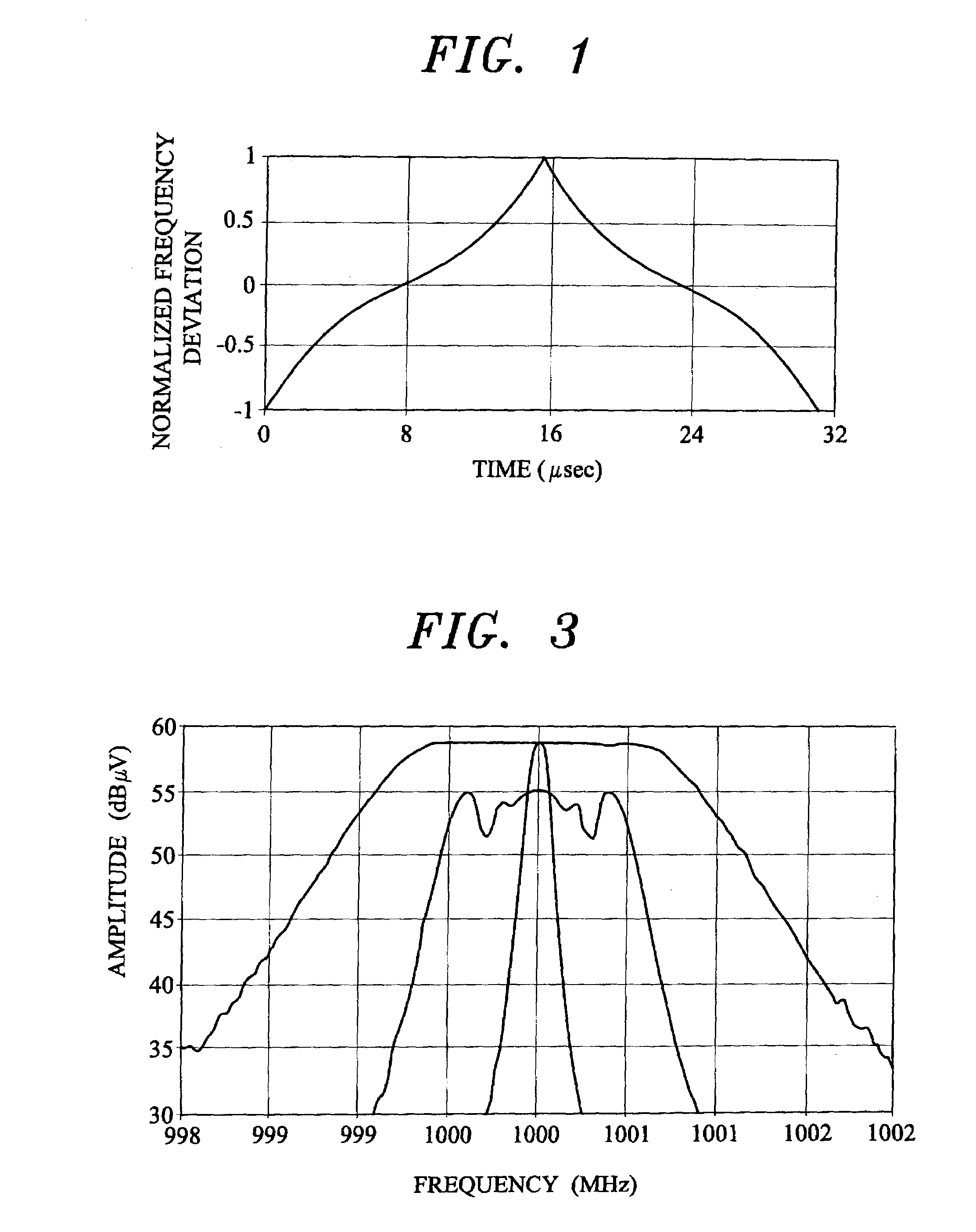
[0034]The results are shown in FIG. 3. Without modulation the clock of the foregoing had a measured amplitude of 58.89 dBμV (central curve). After modulation of the foregoing at measurement bandwidth of 120 kHz the highest point in the spread spectrum harmonic measured 55.25 dBμV for 3.64 attenuation (middle curve). After modulation of the foregoing at measurement bandwidth of 1 MHz the resulting attenuation was 0 dB since the sprea...

Example

TEST EXAMPLE 2

[0035]The foregoing Test Example 1 was modified by increasing the deviation alone by 8.33 times for a deviation of ±2.5 MHz (±0.25%). The results are shown in FIG. 4. The resulting measurement of the modulated clock was 58.76 dBuV (wide curve). The unmodulated clock measured 59 dBμV (central curve). (The tiny variation from the previous measurement was due to the time between measurements.) This gives a negligible attenuation of only 0.24 dB.

[0036]In order to achieve greater attenuation, a much wider deviation would need to be used.

Operative Example

[0037]The foregoing Test Example 2 was modified by increasing the modulation frequency by 8.33 times as follows:[0038]Clock nominal (center) frequency—1 GHz.[0039]Modulation frequency—260 kHz.[0040]Profile (as foregoing Test Examples).[0041]Deviation—±2.5 MHz (±0.25%).[0042]Bandwidth of measurement—1 MHz.

[0043]The results are shown in FIG. 5. The unmodulated clock measured 58.76 dBμV (central curve) and the modulated clock m...

Example

[0048]A third embodiment is applicable to clock frequencies higher than those common currently, but less than 1 GHz. In the near future it can be expected that such clock frequencies, such as 500 MHz, will be used commercially in common devices such as printers. Such clocks will have very significant harmonics above 1 GHz.

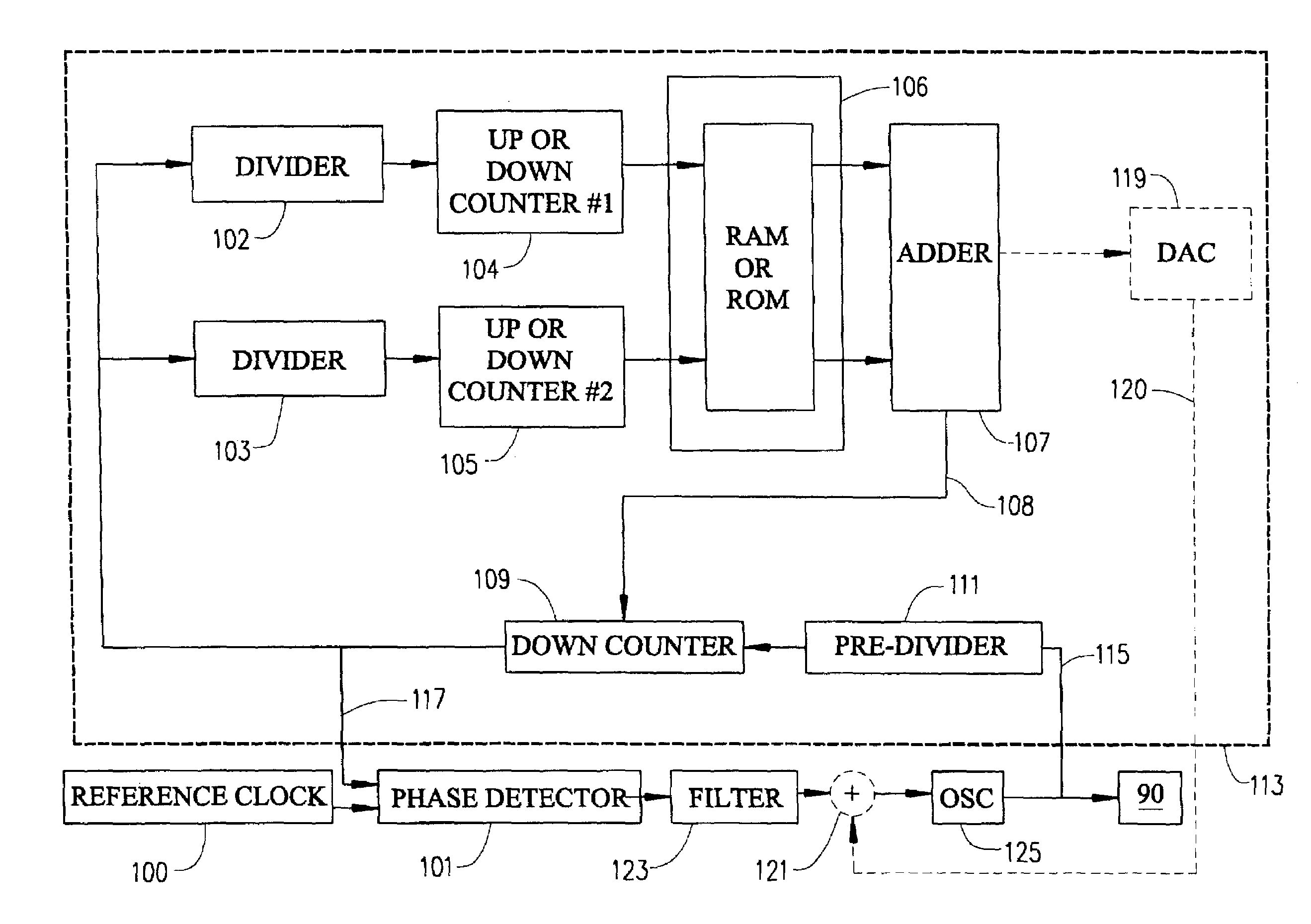
[0049]This embodiment introduces the increased deviation and fast modulation described in the foregoing as a component of the standard modulation to the clock operating below 1 GHz creating a dual modulation profile. FIG. 1 shows the current typical 32 kHz operating in the preferred profile discussed in the foregoing. FIG. 6 shows the high frequency profile to be added to standard modulation. FIG. 8 shows the combined profile.

[0050]The combined profile may be described mathematically as follows:

c(t)=A(t)×M1(ω×t)+B(t)×M2(k×ω×t+φ)

Where: x denotes multiplication,[0051]A is a factor defining the frequency deviation of the slower profile,[0052]B is a factor defining the...


PUM


Abstract

For EMI reduction the current modulation profile is preferably used for frequencies over 1 GHz while the frequency deviation is increased at least to ±2.5 MHz and the modulation frequency is increased to at least 150 kHz, preferably about 260 kHz. In an alternative embodiment, the modification frequency is 1 MHz or greater so that a segmented spectrum is achieved. For clocks having basic frequency below 1 GHz, but having strong harmonics higher than 1 GHz, modulation of the foregoing is combined with the slower modulation currently used. EMI reduction is realized both at the lower and the higher harmonics.

Description

TECHNICAL FIELD[0001]This invention relates to the field of digital circuits, and more particularly, to spread spectrum clock circuits operable at high frequencies having reduced measurable electromagnetic interference (EMI) emissions.BACKGROUND OF THE INVENTION[0002]Spread spectrum clocking is now widely used in the form introduced by U.S. Pat. No. 5,488,627, assigned to the assignee to which this invention is assigned. U.S. Pat. No. 5,631,920, also assigned to the assignee to which this invention is assigned, is directed to digital implementation and control of such circuits. U.S. Pat. No. 6,404,834, also assigned to the assignee to which this invention is assigned, is to spread spectrum clock signals which are segmented by at least 10 dB reductions so as to meet certain proposed CISPR-22 rules.[0003]As processor clock speeds continually increase, the need for methods to mitigate electromagnetic interference (EMI) become more important. Previous methods have been designed for cloc...

Claims


Application Information

Patent Timeline
IPC IPC(8): H04L7/02H03D3/24G06F1/04H04B1/69
CPCG06F1/04
Inventor HALL, PAUL KEVINHARDIN, KEITH BRYANMENKE, ROBERT ALLANOGLESBEE, ROBERT AARON
Owner LEXMARK INT INC
Why Eureka
Try Eureka