Optical communication apparatus

a communication apparatus and optical technology, applied in the field of optical communication apparatuses, can solve the problems of difficult control of the operating point of the optical modulator appropriately, drift generation, interference-type optical modulation element operation point, etc., and achieve the effect of removing noise from a synchronous detection signal

Inactive Publication Date: 2009-07-14
FUJITSU LTD
View PDF9 Cites 21 Cited by
  • Summary
  • Abstract
  • Description
  • Claims
  • Application Information

AI Technical Summary

Benefits of technology

[0025]In view of the foregoing, it is an object of the present invention to provide an optical communication apparatus which can appropriately control the operating point of an optical modulator by extracting noise from an optically modulated pilot signal and eliminating noise from a synchronous detection signal.

Problems solved by technology

The operating point of the interference-type optical modulation element, however, varies with time or varies with the applied voltage or the like, and a drift is generated.
If noise is large for the optically-modulated pilot signal, the signal output from a synchronous detection circuit (the multiplier 152 and the LPF 154, in the above case) contains an offset caused by the noise, and it is hard to control the operating point of the optical modulator appropriately.

Method used


Image

  • Optical communication apparatus
  • Optical communication apparatus
  • Optical communication apparatus

Examples


first embodiment

[0055]the present invention will be described below in detail with reference to the drawings.

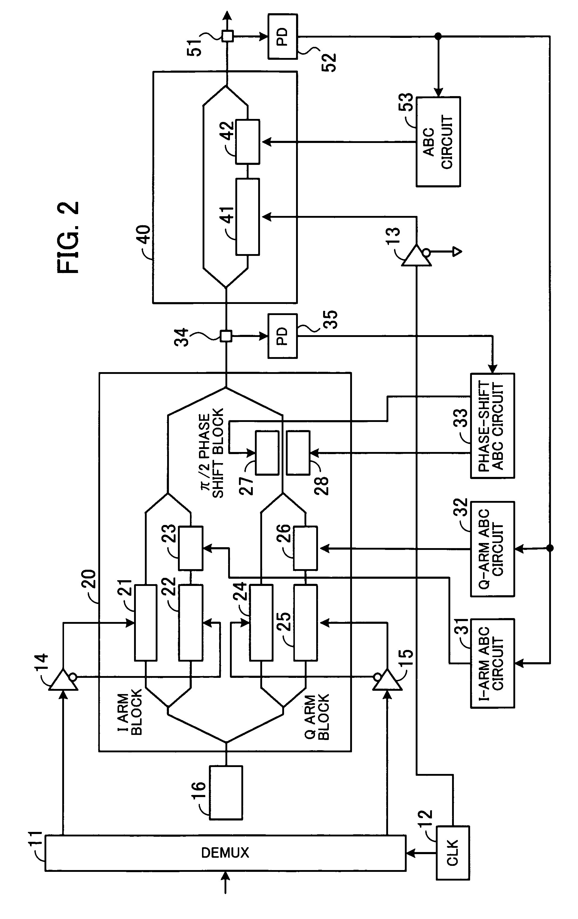
[0056]FIG. 2 is a block diagram showing the configuration of an optical communication apparatus of the first embodiment. The shown optical communication apparatus corresponds to the O / E 101a, the light source 102a, and the optical modulator 103a of the WDM transmission block, described with reference to FIG. 12. The shown optical communication apparatus performs optical modulation of an electrical signal and outputs the signal to the optical multiplexer 104.

[0057]A DEMUX 11 receives an electrical signal transmitted to the WDM reception block. The electrical signal input to the DEMUX 11 is a 43-Gb / s signal, for instance. The DEMUX 11 also receives a 21.5-GHz clock from a CLK 12, divides the input electrical signal into two 21.5-Gb / s signals, and outputs the signals to amplifiers 14 and 15, for instance.

[0058]The amplifier 14 amplifies an electrical signal output from one end of the DEMUX 11 a...

second embodiment

[0097]FIG. 8 is a block diagram showing the configuration of an optical communication apparatus of the In FIG. 8, circuits identical to those shown in FIG. 7 are denoted by the same reference numerals, and a description thereof is omitted.

[0098]A phase shifter 91 adjusts the phase of the pilot signal output from the pilot signal generator 64 so that the signal becomes in phase with the pilot signal output from the ADC 72, and outputs the signal to a multiplier 73 as a reference signal. The phase shifter 91 also outputs a reference signal 90° out of phase from the reference signal output to the multiplier 73 to a multiplier 92.

[0099]Suppose that the phase shifter 91 outputs a reference signal “a” degrees out of phase from the pilot signal to the multiplier 73. The phase shifter 91 outputs a reference signal (a+90) degrees out of phase from the pilot signal to the multiplier 92. Alternatively, the phase shifter 91 outputs a reference signal (a−90) degrees (=(a+270) degrees) out of ph...

third embodiment

[0108]FIG. 10 is a block diagram showing the configuration of an optical communication apparatus of the In FIG. 10, circuits identical to those shown in FIG. 7 are denoted by the same reference numerals, and a description thereof will be omitted.

[0109]In FIG. 10, the BPF 70 included in FIG. 7 is omitted. The output of the demodulator 69 is given to the AMP 71 and BEF 81.

[0110]The multiplier 73 and LPF 75 perform synchronous detection of the pilot signal and also function as a BPF. When a great influence of noise is found in the synchronous detection of the pilot signal, the BPF 70 can be disposed after the demodulator 69, as shown in FIG. 7, in order to remove signals having frequencies other than 1 kHz.

[0111]The BPF 70 can be omitted if the influence of noise is small. Accordingly, the number of components can be reduced.

[0112]If a direct-current voltage is applied to the output of the demodulator 69, a circuit for removing the direct-current component is disposed after the demodu...


PUM

PropertyMeasurementUnit
center frequencyaaaaaaaaaa
bias voltageaaaaaaaaaa
frequencyaaaaaaaaaa

Abstract

An optical communication apparatus for controlling the operating point of an optical modulation unit appropriately. An adding unit adds a bias voltage and a pilot signal. An optical modulation unit modulates light by an electrical signal, performs further modulation by a signal from the adding unit, and outputs an optical signal. A monitor unit monitors the level of the optical signal and outputs a monitor signal. A reference signal output unit outputs a reference in phase with the pilot signal contained in the monitor signal. A synchronous pilot-signal detection unit performs synchronous detection of the monitor signal by using the reference. A synchronous noise detection unit extracts noise from the monitor signal and performs synchronous detection of the noise by using the reference. A control signal output unit subtracts the synchronous detection value of the noise from that of the monitor signal, and outputs a control signal.

Description

CROSS-REFERENCE TO RELATED APPLICATIONS[0001]This application is based upon and claims the benefits of priority from the prior Japanese Patent Application No. 2006-141530, filed on May 22, 2006, the entire contents of which are incorporated herein by reference.BACKGROUND OF THE INVENTION[0002]1. Field of the Invention[0003]The present invention relates to optical communication apparatuses, and particularly to an optical communication apparatus which modulates an electrical signal to an optical signal and transmits the optical signal.[0004]2. Description of the Related Art[0005]Current multimedia networks require optical communication apparatuses that can cover a very long distance and have a high capacity. Current optical communication apparatuses use an optical modulator as an electrical-optical converter.[0006]FIG. 12 shows the configuration of an optical communication system. As shown in the figure, the optical communication system can be divided into a wavelength division multip...

Claims


Application Information

Patent Timeline
Patent Type & Authority Patents(United States)
IPC IPC(8): H04B10/04H04B10/12G02F1/03H04B10/07H04B10/516H04B10/548H04B10/61
CPCH04B10/505H04B10/50577H04B10/50575H04B10/5051
Inventor NOGUCHI, MASAJIUENO, TOMOHIRO
Owner FUJITSU LTD
Why Eureka
Try Eureka