Driving control apparatus of rotary brush for use in vacuum cleaner

a technology of rotary brushes and control apparatuses, which is applied in the direction of vacuum cleaners, carpet cleaners, and domestic applications, can solve the problems of inability to accurately control the drive the tensile force of the driving belt is not overcome, and the operation of the rotary brush cannot be accurately controlled. it can prevent damage to parts

Inactive Publication Date: 2009-07-21
SAMSUNG GWANGJU ELECTRONICS CO LTD
View PDF6 Cites 7 Cited by
  • Summary
  • Abstract
  • Description
  • Claims
  • Application Information

AI Technical Summary

Benefits of technology

[0008]The present disclosure has been developed in order to solve the above problems in the related art. Accordingly, an aspect of the present disclosure is to provide a driving control apparatus of a rotary brush capable of preventing a damage to parts caused by a friction force generated during a driving force transmitting and blocking operation to the rotary brush.
[0009]Another aspect of the present disclosure is to provide a driving control apparatus of a rotary brush capable of more stably and accurately carrying out a driving force transmitting and blocking operation to the rotary brush.
[0010]The above aspects are achieved by providing a driving control apparatus of a rotary brush including a fixing bracket disposed in a suction body of a vacuum cleaner, a link unit pivotably connected to the fixing bracket, a pedal unit connected to one side of the link unit, and a pulley unit to move in combination with the link unit and to connect or separate a driving belt to or from a driving shaft. The pulley unit is rotated in the same direction as a rotating direction of the driving belt when coming in contact with the driving belt. Accordingly, a friction of contact parts between the pulley unit and the driving belt is reduced, so that the pulley unit or the driving belt is prevented from being damaged due to an excessive friction force between the pulley unit and the driving belt.

Problems solved by technology

As a result, the contact portions of the driving belt and the belt extending rack generate a high temperature of heat, and thus a portion of the driving belt is damaged or in the worst case, the driving belt is cut, so that it cannot control a drive of the rotary brush.
If an elastic force of the leaf spring is deteriorated, the leaf spring does not overcome a tensile force of the driving belt.
Thus, a problem may occur, in that it is impossible to accurately control a driving force transmitting and blocking operation to the rotary brush.

Method used


Image

  • Driving control apparatus of rotary brush for use in vacuum cleaner
  • Driving control apparatus of rotary brush for use in vacuum cleaner
  • Driving control apparatus of rotary brush for use in vacuum cleaner

Examples


Embodiment Construction

[0024]Hereinafter, a driving control apparatus of a rotary brush according to an exemplary embodiment of the present disclosure will now be described in greater detail with reference to the accompanying drawing figures.

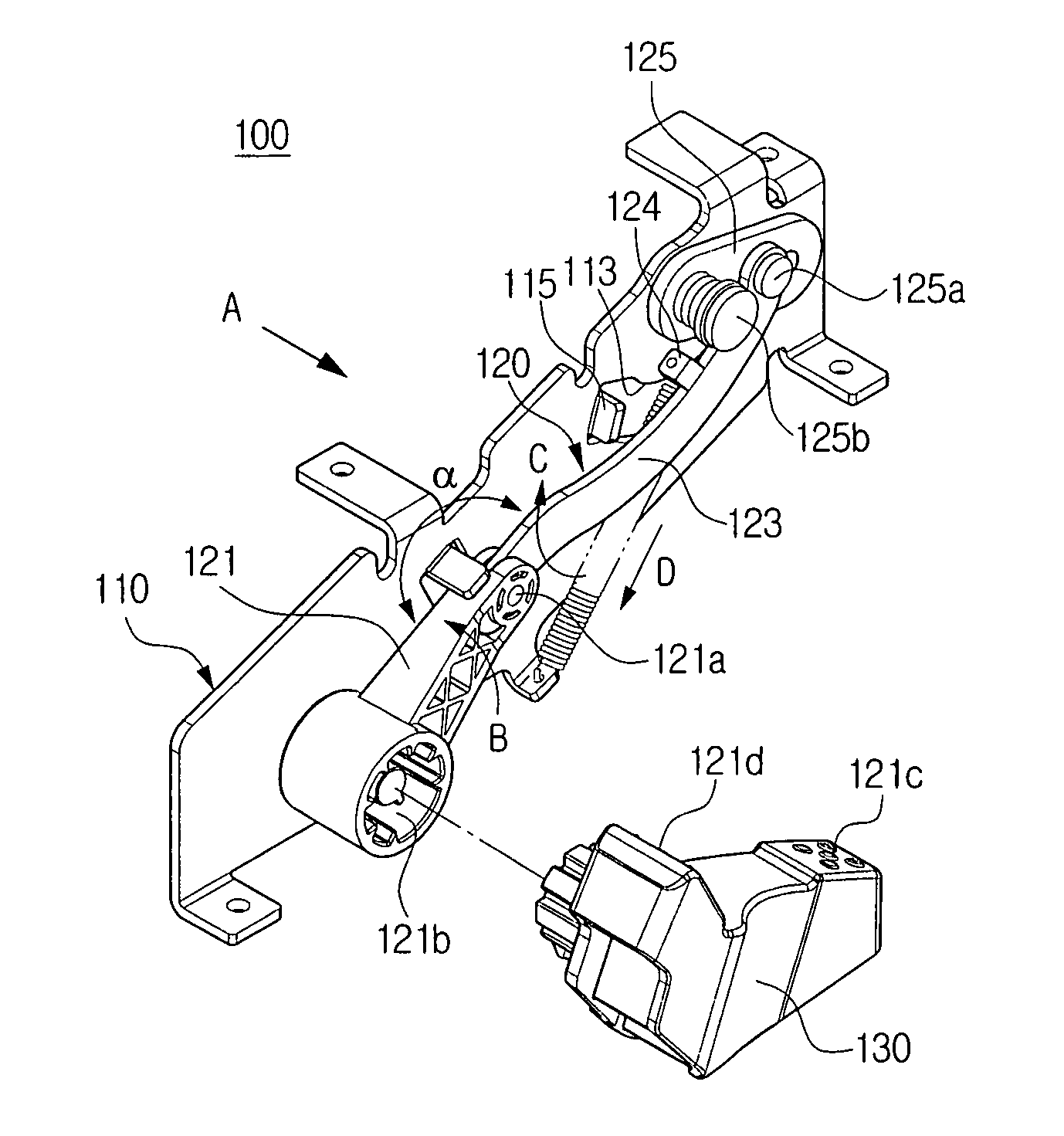
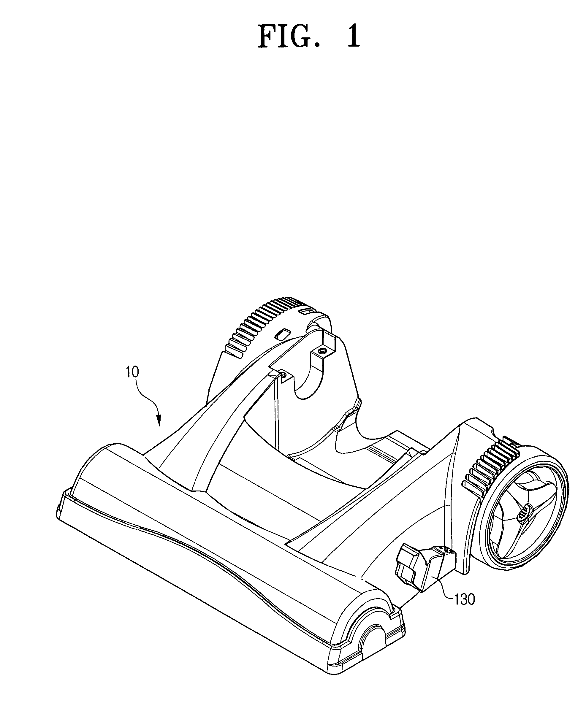
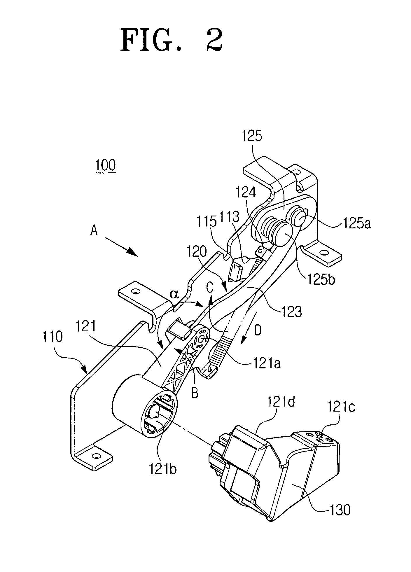
[0025]FIG. 1 is a schematic perspective view exemplifying a suction body in which a driving control apparatus of a rotary brush according to an exemplary embodiment of the present disclosure is mounted, FIG. 2 is a perspective view exemplifying the driving control apparatus of the rotary brush, FIG. 3 is a perspective view of the driving control apparatus of the rotary brush as viewed from a direction of arrow A of FIG. 2, and FIG. 4 is an exploded perspective view exemplifying a second arm and a pulley unit illustrated in FIG. 2.

[0026]Referring to FIGS. 1 through 4, the driving control apparatus 100 of the rotary brush according to the exemplary embodiment of the present disclosure includes a fixing bracket 110, a link unit 120, a pedal unit 130, and a pulley unit 14...


PUM


Abstract

A driving control apparatus of a rotary brush, which controls a drive of the rotary brush disposed in a suction body of a vacuum cleaner, is disclosed. The driving control apparatus includes a fixing bracket disposed in a suction body of a vacuum cleaner, a link unit pivotably connected to the fixing bracket, a pedal unit connected to one side of the link unit, and a pulley unit to move in combination with the link unit and to connect or separate a driving belt to or from a driving shaft, and the pulley unit is rotated in the same direction as a rotating direction of the driving belt when coming in contact with the driving belt.

Description

CROSS-REFERENCE TO RELATED APPLICATIONS[0001]This application claims the benefit under 35 U.S.C. § 119(a) of Korean Patent Application No. 2006-0088917, filed on Sep. 14, 2006, in the Korean Intellectual Property Office, the entire disclosure of which is incorporated herein by reference.BACKGROUND OF THE INVENTION[0002]1. Field of the Invention[0003]The present disclosure relates to a driving control apparatus of a rotary brush, and more particularly, to a driving control apparatus of a rotary brush, which controls a drive of the rotary brush installed in a suction body of a vacuum cleaner.[0004]2. Description of the Related Art[0005]As disclosed in Korean patent No. 279,667, a conventional driving control apparatus of a rotary brush is configured, so that the rotary brush rotated by receiving a driving force from a motor driving shaft through a driving belt, one side of which is connected to the motor driving shaft and the other side of which is connected to one side of the rotary ...

Claims


Application Information

Patent Timeline
Patent Type & Authority Patents(United States)
IPC IPC(8): A47L5/30
CPCA47L9/0444A47L5/30A47L9/04A47L9/06A47L11/204
Inventor MOON, JOO-SUNG
Owner SAMSUNG GWANGJU ELECTRONICS CO LTD
Why Eureka
Try Eureka