
High-voltage wire harness

a high-voltage wire harness and wire harness technology, applied in the direction of insulated conductors, cables, power cables, etc., can solve the problems of high cost and high cost of high-voltage wire harnesses, and achieve the effects of low cost, low cost and prevent accidental short-circuiting

Active Publication Date: 2009-07-21
YAZAKI CORP
View PDF15 Cites 29 Cited by
  • Summary
  • Abstract
  • Description
  • Claims
  • Application Information

AI Technical Summary

Benefits of technology

[0011]Therefore, this invention has been made in order to solve the above problem, and an object of the invention is to provide a high-voltage wire harness with a shielding performance which is low in cost.
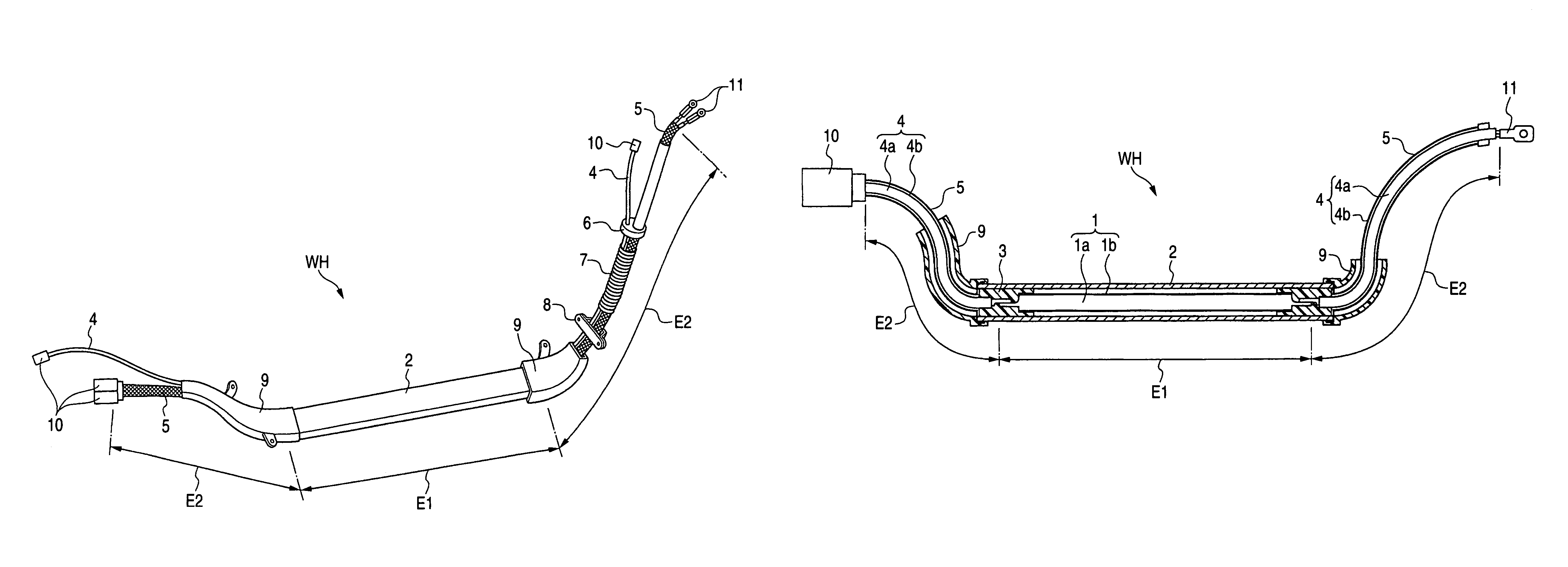
[0017]According to the aspect of the present invention, the inexpensive rigid wires, each having the single conductor, are employed in the installation path region where the cable is not required to have flexibility, and the rigid wires are covered at their outer peripheries with the metal shielding case, thereby securing the shielding performance. On the other hand, the inexpensive flexible wires are employed in the installation path region where the cable is required to have flexibility, and the flexible wires are covered at their outer peripheries with the expensive flexible shielding member, thereby securing the shielding performance. Thus, the expensive flexible shielding member is used only at the limited region, and therefore the wire harness with the shielding performance can be produced at a low cost.
[0018]According to the aspect of the present invention, the rigid wires can be produced at a very low cost, and besides the insulating sheath can prevent the accidental short-circuiting between the adjacent rigid wires.
[0019]According to the aspect of the present invention, connectors and terminals are connected to the ends of the flexible wires, and therefore operations for connecting the connectors and the terminals can be carried out efficiently.
[0020]According to the aspect of the present invention, the metal protector, protecting the rigid wires, serves also to achieve the shielding performance, and this further reduces the cost. And besides, in the case where the wire harness is installed in a vehicle body, the metal protector is fixed to the vehicle body, and therefore it is not necessary to provide a ground-connecting portion and also to carry out an additional operation for grounding the wire harness to the vehicle body.
[0021]According to the aspect of the present invention, the flexible shielding members can be easily and positively connected to the metal protector. And besides, the flexible shielding members are protected by the resin protectors, and therefore an accident, such as the cutting of the wires and damage of the flexible shielding members, can be positively prevented.

Problems solved by technology

However, the flexible shielding member (e.g., a braid formed by weaving metal wires into a tubular shape) is expensive, and this expensive shielding member need to be provided over the entire length of the wires, and therefore the high-voltage wire harness becomes very expensive.
In the conventional high-voltage wire harness 50, however, the expensive shielded wires W2 are used over the entire length of the installation path, and therefore there has been encountered a problem that the cost is very high as is the case with the first-mentioned conventional high-voltage wire harness.

Method used


Image

  • High-voltage wire harness
  • High-voltage wire harness
  • High-voltage wire harness

Examples


Embodiment Construction

[0029]One preferred embodiment of the present invention will now be described with reference to the drawings.

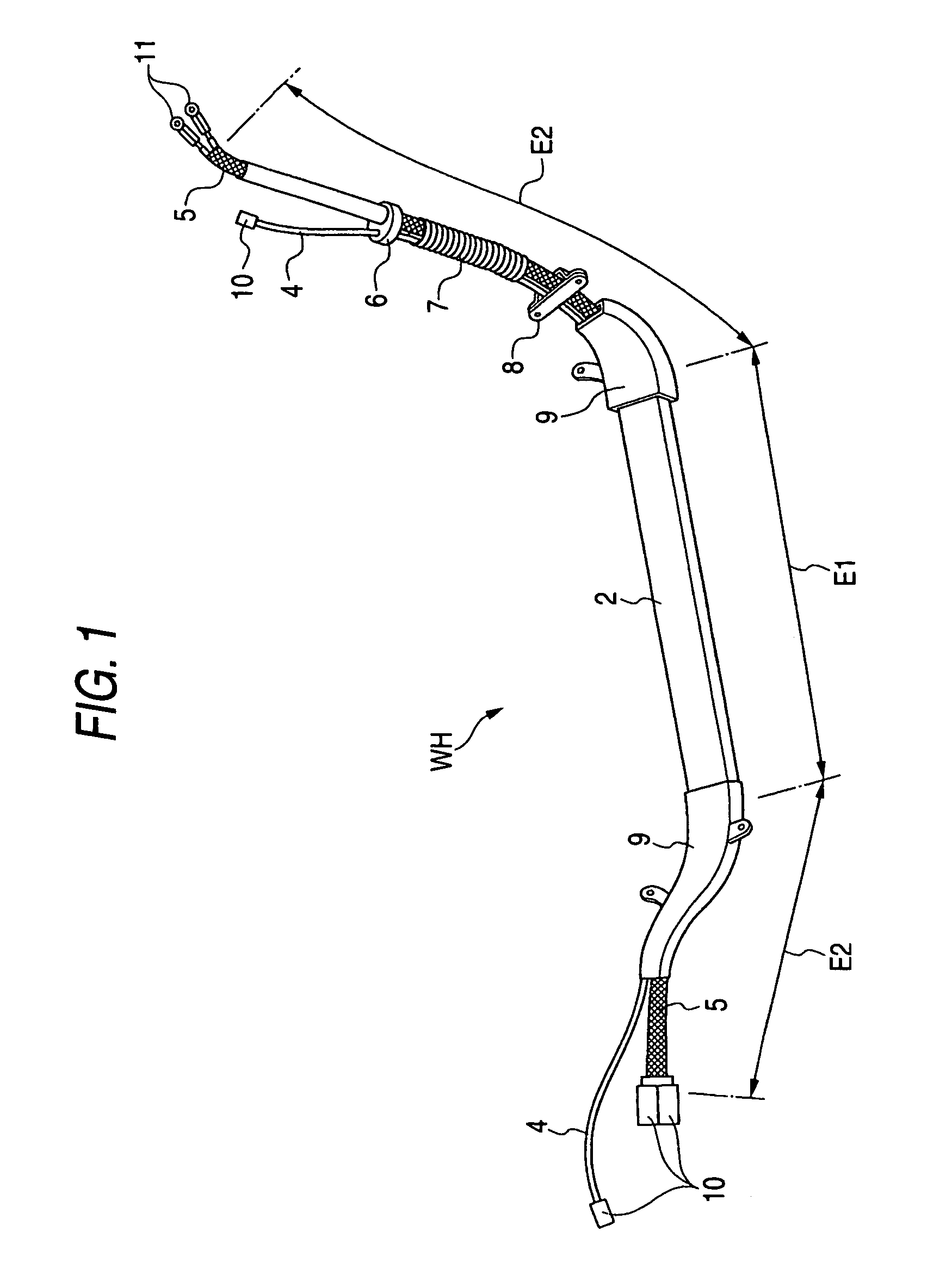
[0030]As shown in FIG. 1, a path of installation of the high-voltage wire harness WH is divided into a straight installation path region E1 (where a cable is not required to have flexibility) and installation path regions E2 (where the cable is required to have flexibility) disposed respectively at opposite ends of the region E1. That portion of the wire harness WH, corresponding to the central installation path region E1, is fixed to a vehicle body via a metal protector 2, and therefore does not need to have flexibility. Operations for connecting connectors 10 and LA terminals 11 are effected at the installation path regions E2 disposed respectively at the opposite ends of the central installation path region E1, and therefore those portions of the wire harness WH, corresponding respectively to the installation path regions E2, need to have flexibility. The portions of the h...


PUM


Abstract

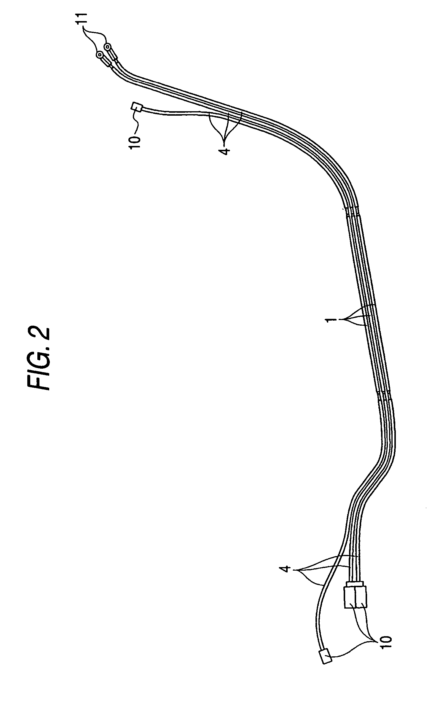
That portion of a wire harness, corresponding to an installation path region E1 where a cable is not required to have flexibility, includes rigid wires 1 each having a single conductor 1a, and a metal shielding case 2 covering outer peripheries of the rigid wires 1. Each of those portions of the wire harness, corresponding respectively to installation path regions E2 where the cable is required to have flexibility, includes flexible wires 4, and a flexible shielding member 5 covering outer peripheries of the flexible wires 4. Conductors 4a of the flexible wires 4 are connected to the conductors 1a of the rigid wires 1, and the metal protector 2 is connected to the flexible shielding members 5.

Description

BACKGROUND OF THE INVENTION[0001]1. Field of the Invention[0002]This invention relates to a high-voltage wire harness having a shielding performance.[0003]2. Related Art[0004]When a source voltage for an automobile is increased to a high level, wires of a wire harness can be reduced in diameter, and also the efficiency of use of a power source, etc., can be improved. On the other hand, it becomes necessary to take a positive measure to cope with electromagnetic noises which affect a high-voltage wire harness (used, for example, between a battery and an inverter or between a motor and an inverter).[0005]There is one conventional high-voltage wire harness with a shielding performance in which non-shielded type wires with no shielding layer are used, and a bundle of these wires are collectively covered at an outer periphery thereof with a single shielding member (see, for example, JP-A-2003-197037).[0006]However, the flexible shielding member (e.g., a braid formed by weaving metal wire...

Claims


Application Information

Patent Timeline
IPC IPC(8): H01B7/00H01B7/08H01P3/06H02G15/25H02G3/04H02G5/06
CPCB60R16/0215H02G3/0462B60L2270/147H01B7/0045
Inventor ICHIKAWA, HIDEHIROHASHIZAWA, SHIGEMI
Owner YAZAKI CORP
Learn More