Light emission device and method utilizing multiple emitters and multiple phosphors
a technology of light emission device and phosphor, which is applied in the direction of discharge tube luminescnet screen, lighting and heating apparatus, light source combination, etc., can solve the problem that the phosphor device for white light production does not provide high conversion efficiency color rendering in various spectral regimes
- Summary
- Abstract
- Description
- Claims
- Application Information
AI Technical Summary
Benefits of technology
Problems solved by technology
Method used
Image
Examples
example 1
Light Emission Device Including Two Visible Light LEDs and Two Phosphors
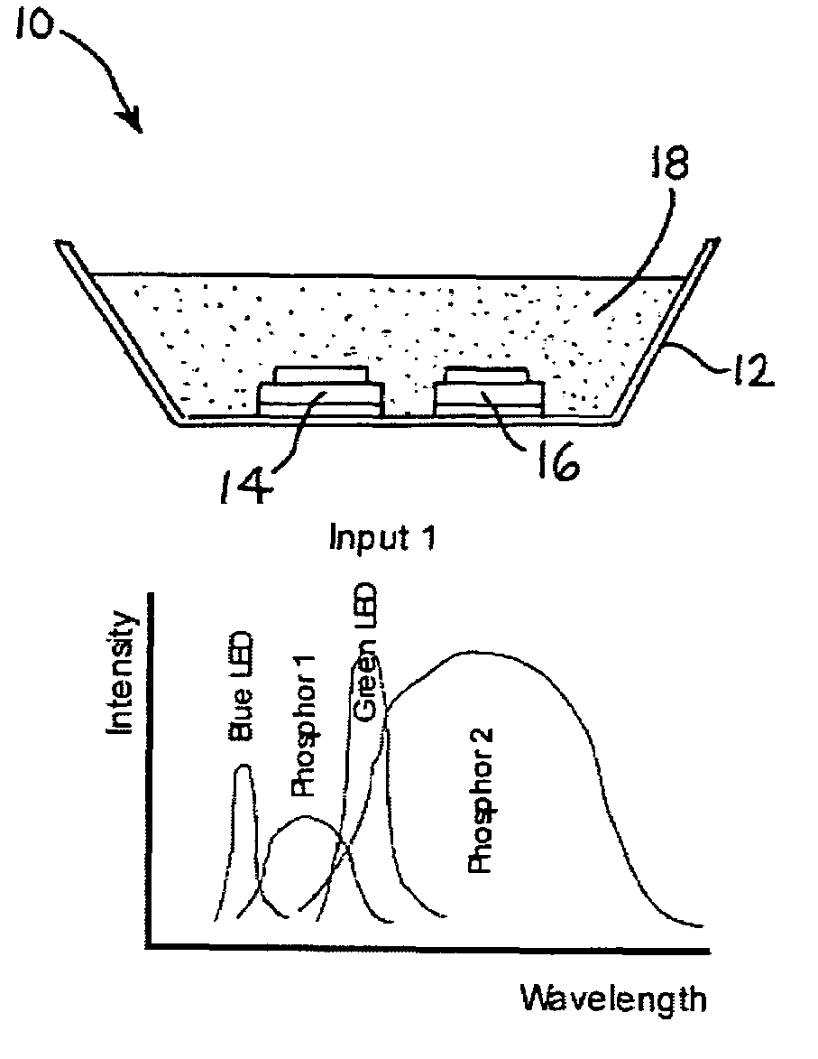
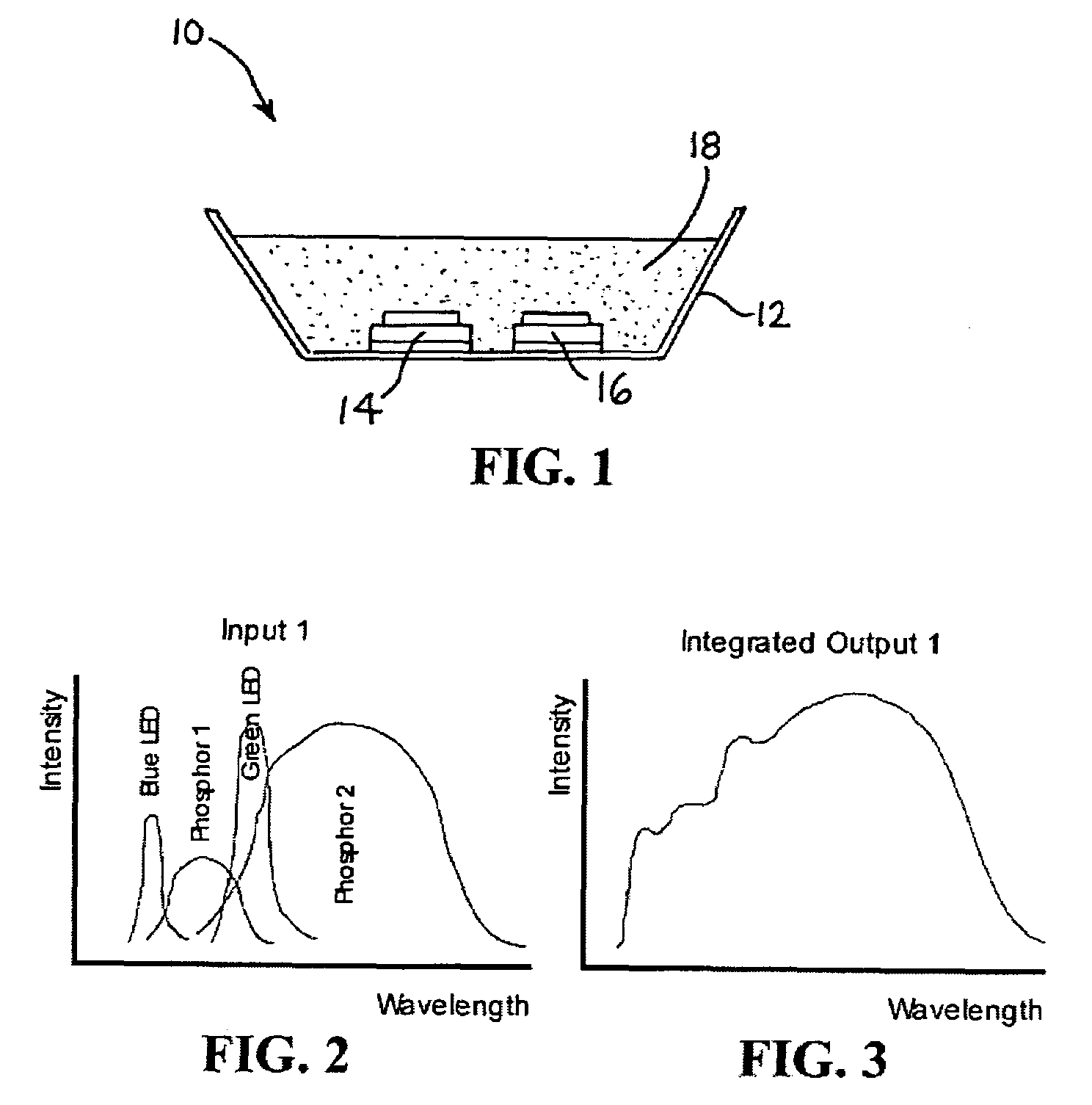
[0067]To encompass the desired spectral range, two LEDs, an X-Brite deep blue (having a spectral output centered at 460 nm and extending between ˜440 nm and ˜480 nm) LED and an X-Brite green (having a spectral output centered at 527 nm and extending between ˜500 nm and ˜560 nm) LED, both commercially available from Kingbright Corporation, Taipei, Taiwan, are utilized to fabricate a light emission device of the type shown in FIG. 2. The LEDs function as light sources and excite a phosphor mixture including two phosphors. The first phosphor in the phosphor mixture is a CaGa2S4:Eu2+ phosphor, which emits a yellowish-green light and which is excited with light having a wavelength shorter than 510 nm (˜50% absorption). The second phosphor in the phosphor mixture is a ZnGa2S4:Mn2+ phosphor, which emits an orange-red light and which is excited by light having a wavelength shorter than about ˜480 nm (˜25% absorption). T...
example 2
Blue and Red LEDs with Two Phosphors Excited Only by the Blue
[0070]To encompass the desired spectral range, two LEDs, an X-Brite deep blue (460 nm) LED and an X-Brite red (670 nm) LED, both commercially available from Kingbright Corporation, Tapei, Taiwan, are utilized to fabricate a light emission device of the type shown in FIG. 2. The LEDs function as light sources and the blue is used to excite a phosphor mixture including two phosphors. The first phosphor in the phosphor mixture is a SrSCu+,Na phosphor, which emits a green light centered on 530 nm and which is excited with light shorter than ˜490 nm (˜20% absorption). The second phosphor in the phosphor mixture is a CaSO4:Bi phosphor, which emits a yellow orange light and which is excited by light shorter than about 510 nm (˜10% absorption). The LED dies are coated by the phosphors during manufacture, with all dies being mounted in a single package to facilitate fabrication and assembly. The phosphors are excited by the blue li...
example 3
Ultraviolet and Blue LEDs and One Phosphor
[0072]To encompass the desired spectral range approaching a solar spectrum, two LEDs, a MegaBrite ultraviolet (having output centered at 395 nm) LED, commercially available from Cree, Inc., Durham, N.C., USA, and an X-Brite signal green (having output centered at 505 nm) LED, commercially available from Kingbright Corporation, Taipei, Taiwan, are employed to fabricate a light emission device of the general type shown in FIG. 2, in which the phosphor material contains only one phosphor. The ultraviolet LED acts to excite the phosphor while the green LED contributes to the emission to ensure that the spectral distribution produced by the light emission device closely matches the desired solar spectrum. The phosphor employed in the device is a CaMgSi2O6:Eu2+,Mn2+ phosphor, which emits in the blue, yellow-green, orange and red. This phosphor is transmissive to green and the X-Brite signal green LED produces light in this spectral region. The pho...
PUM
 Abstract
Description
Claims
Application Information
 - R&D
- Intellectual Property
- Life Sciences
- Materials
- Tech Scout
- Unparalleled Data Quality
- Higher Quality Content
- 60% Fewer Hallucinations
Browse by: Latest US Patents, China's latest patents, Technical Efficacy Thesaurus, Application Domain, Technology Topic, Popular Technical Reports.
© 2025 PatSnap. All rights reserved.Legal|Privacy policy|Modern Slavery Act Transparency Statement|Sitemap|About US| Contact US: help@patsnap.com


