
Magnetic field detector and a current monitoring device including such a detector

a detector and current monitoring technology, applied in the direction of measurement devices, magnetic measurements, instruments, etc., can solve the problems of insufficient gain to sustain oscillation, inability to maintain oscillation, and inability to adjust the amplitude of oscillation, so as to achieve the effect of altering the response of the sensor

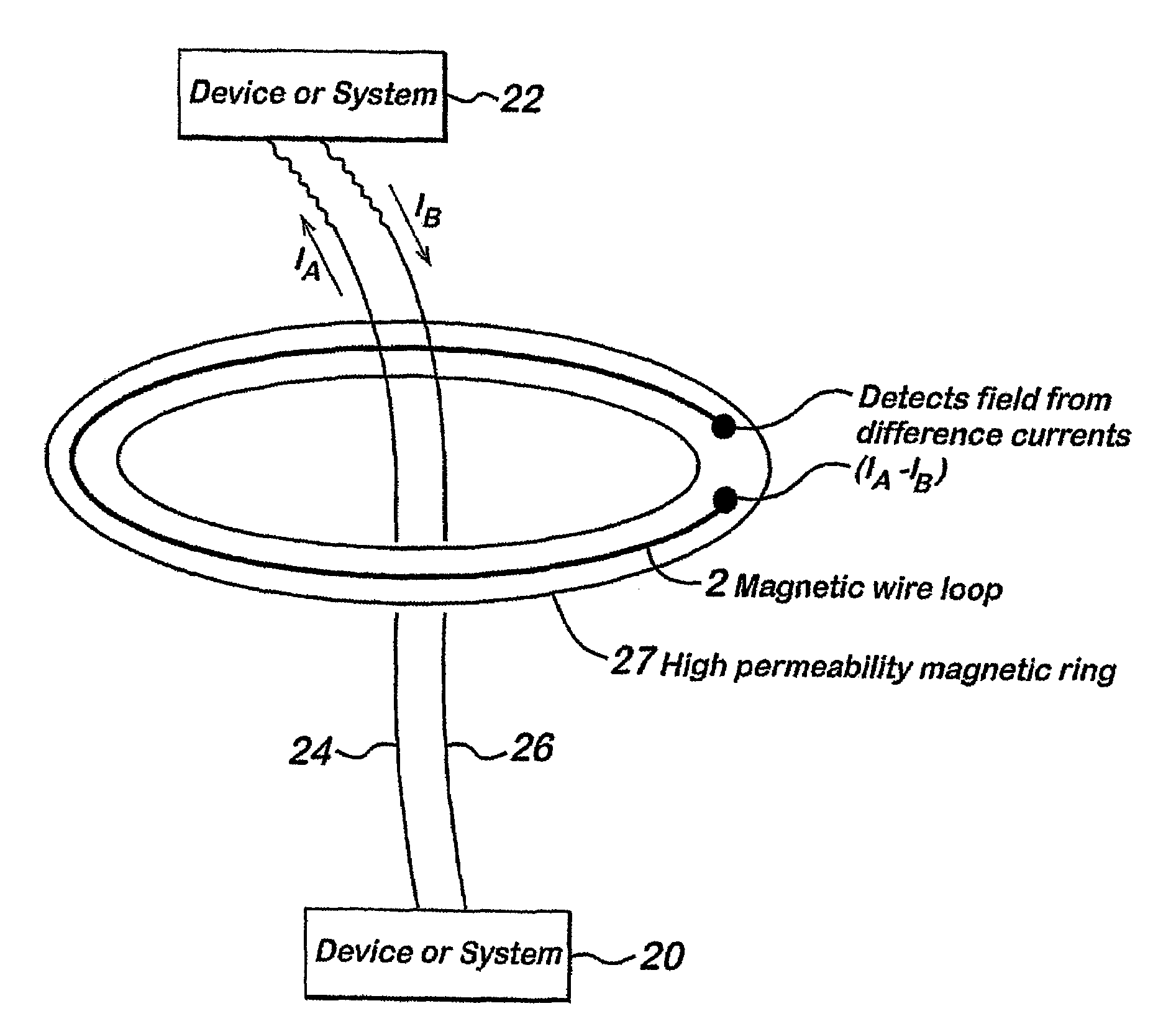
Inactive Publication Date: 2009-07-21
UNIV OF PLYMOUTH
View PDF19 Cites 18 Cited by
  • Summary
  • Abstract
  • Description
  • Claims
  • Application Information

AI Technical Summary

Benefits of technology

[0010]The invention described herein is a magnetic field detector. The magnetic elements are advantageously in the form of a rings or cylinders. Advantageously the sensor may be provided in association with a biasing element so as to alter the response of the sensor. The biasing element may make the sensor more sensitive to a transition in magnetic field strength or may allow the affects of environmental fields to be nulled out. The biasing element may be a permanent magnet, or may be an electromagnet, for example a coil on or adjacent the sensor. Alternatively an AC bias may be provided, for example by a coil adjacent or over the sensor. The coil may be connected in series with the sensor.

Problems solved by technology

Furthermore, the oscillator may be arranged such that it will not sustain oscillation outside of a predetermined operating range.
Thus, for example, if the “gain” of the oscillator is a function of frequency, the gain may be insufficient to sustain oscillation, or the amplitude of the oscillation may vary with the magnetic field strength at the sensor.

Method used


Image

  • Magnetic field detector and a current monitoring device including such a detector
  • Magnetic field detector and a current monitoring device including such a detector
  • Magnetic field detector and a current monitoring device including such a detector

Examples


Embodiment Construction

[0028]Although making and using various embodiments of the present invention are discussed in detail below, it should be appreciated that the present invention provides many inventive concepts that may be embodied in a wide variety of contexts. The specific aspects and embodiments discussed herein are merely illustrative of ways to make and use the invention, and do not limit the scope of the invention.

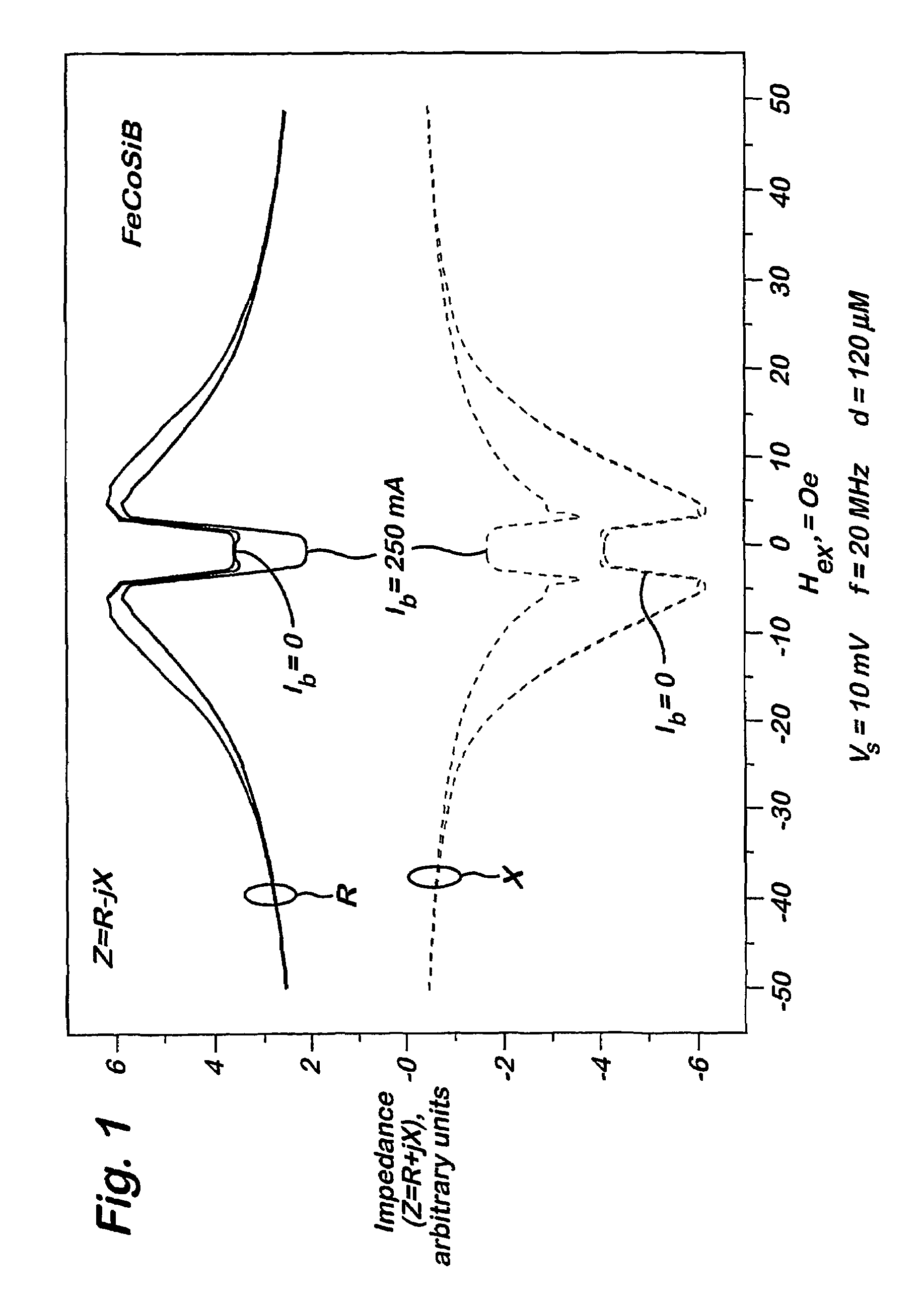
[0029]FIG. 1 represents the impedance of a 3 cm long amorphous wire of CoFeSiB. The wire has a diameter of 120 microns. The measurements of the resistive R and inductive X components of the impedance were made at a frequency of 20 MHz.

[0030]The magnitude of the reactive component X is given by;

X=ωL  (1)

were L is inductance of the wire and ω is the angular frequency of the input signal.

[0031]Two measurements were performed, a first in which no DC current was applied (represented on the graphs by the lines labelled Ib=0) and the second in which a bias current of 250 mA DC was applied, r...


PUM


Abstract

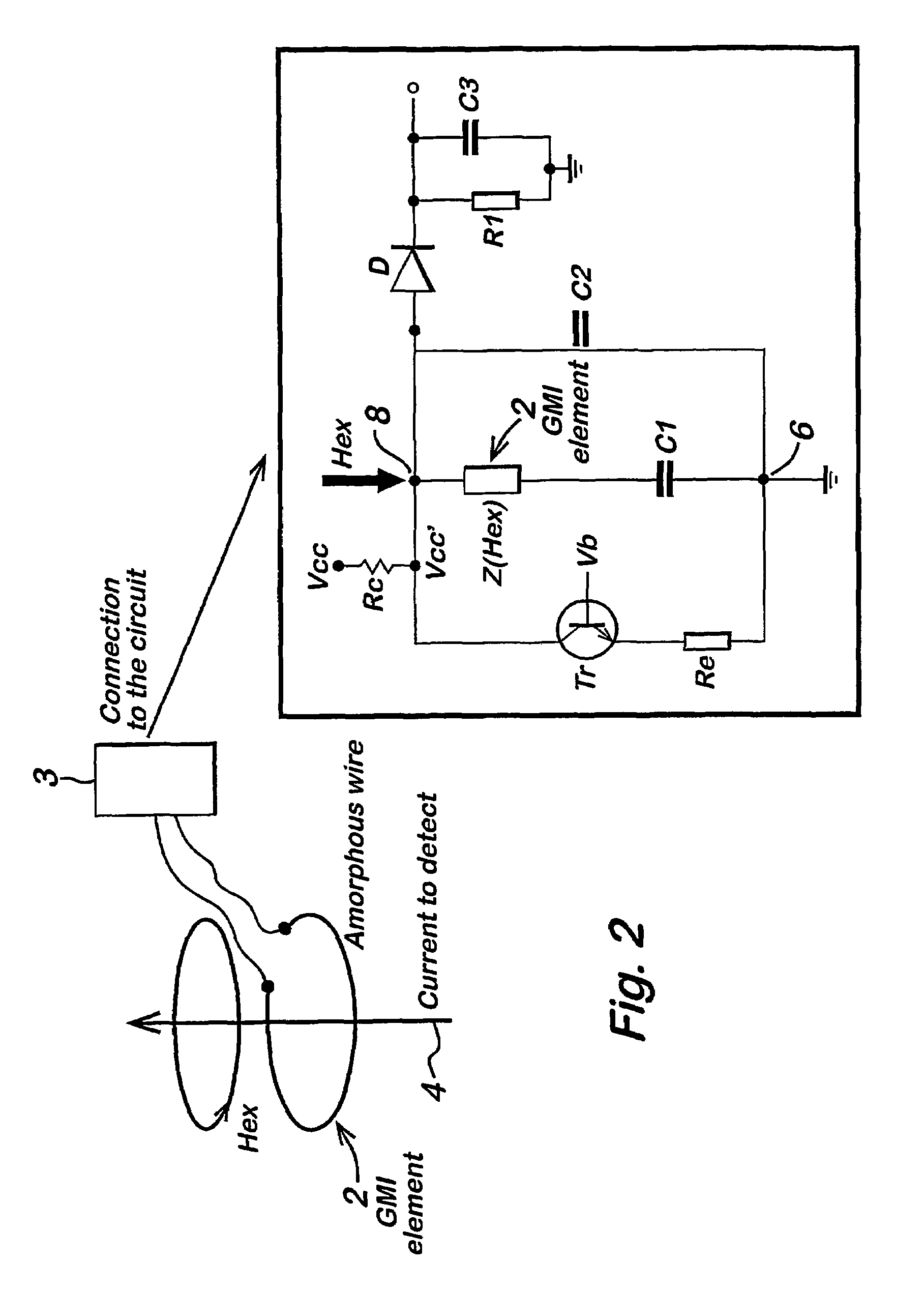
A magnetic field detector is provided that makes use of Magneto-Impedance in order to switch an oscillator between operating states as a function of magnetic field strengths.

Description

CROSS REFERENCE TO RELATED APPLICATIONS[0001]This application claims priority to International Application Number PCT / GB02 / 00299 filed Jan. 24, 2002, which claims the benefit of priority to Application Number 0102602.0 filed Feb. 1, 2001, in the United Kingdom.BACKGROUND OF THE INVENTION[0002]The present invention relates generally to the field of magnetic field detectors and devices, and more specifically to current monitoring devices or current leakage detection devices, including such detectors.[0003]In accordance with the present invention, there is provided a magnetic field detector, comprising a sensor exhibiting an impedance that changes as a function of field strength at the sensor, the sensor comprising at least one wire arranged in a closed path, or a substantially closed path, which in use encircles at least one wire carrying a current, and a measurement device responsive to the impedance of the sensor, characterised in that the sensor is positioned on at least one magnet...

Claims


Application Information

Patent Timeline
Patent Type & Authority Patents(United States)
IPC IPC(8): G01R33/00G01R15/20G01R33/02
CPCG01R33/02
Inventor MAPPS, DESMOND JAMESPANINA, LARISSA V
Owner UNIV OF PLYMOUTH
Learn More