
Controlled compressional wave components of thickness shear mode multi-measurand sensors

a compressional wave and sensor technology, applied in the direction of liquid/fluent solid measurement, instruments, machines/engines, etc., can solve the problems of spurious modes, unwanted devices designed to be ‘single mode’ devices, and inability to simultaneously detect all fluid properties, so as to achieve anti-reflective effect, and altering response of said awd

Inactive Publication Date: 2011-03-24
MICROSEMI CORP HIGH PERFORMANCE TIMING
View PDF57 Cites 11 Cited by
  • Summary
  • Abstract
  • Description
  • Claims
  • Application Information

AI Technical Summary

Benefits of technology

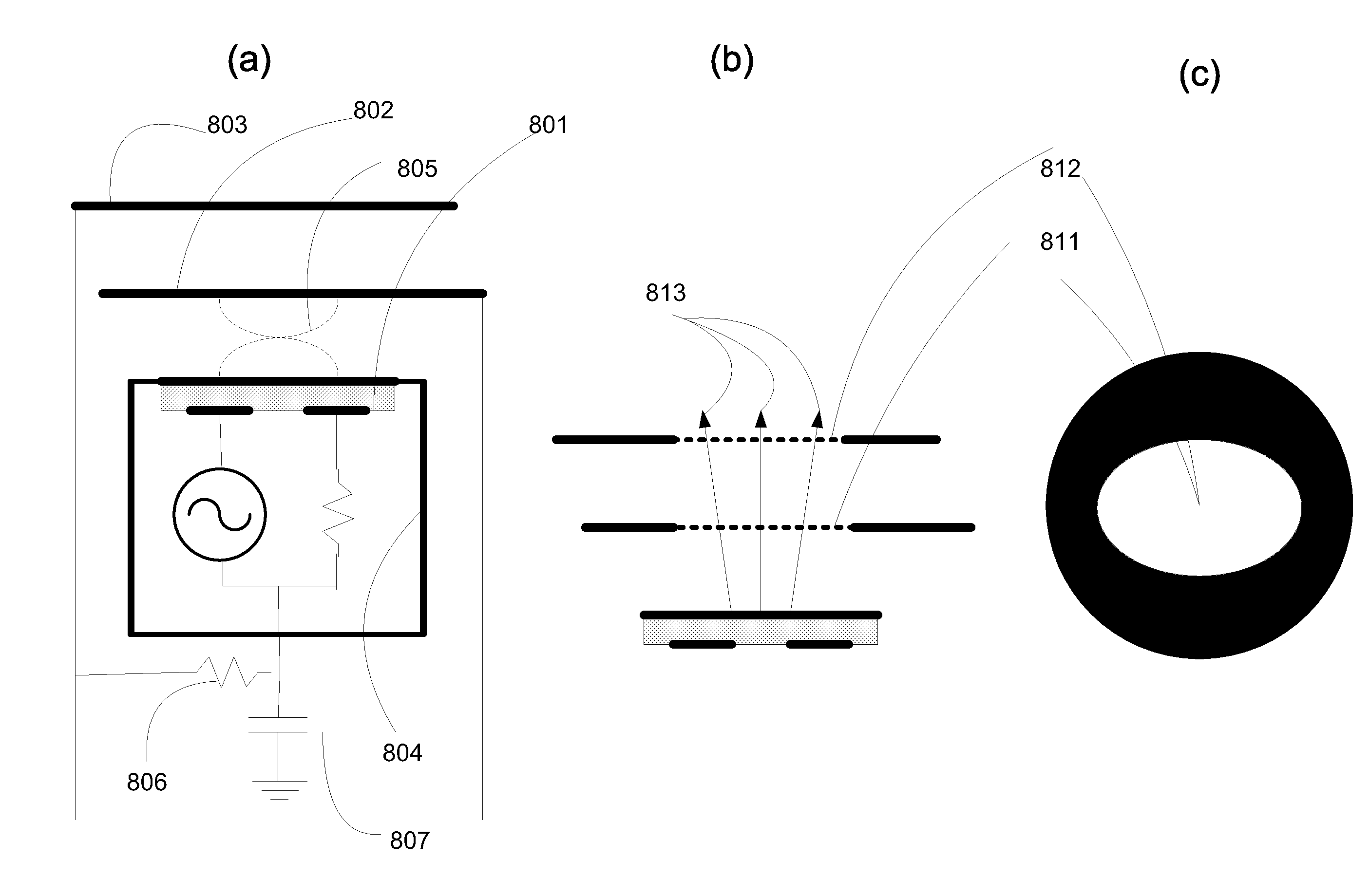
[0058]An acoustic wave device (AWD) sensor for simultaneous determination of fluid properties, said device comprising: at least one solid structure opposite a surface of said AWD, defining finite extents of a fluid to be measured, said structure being anti-reflective to compressional waves propagating away from said surface of said AWD, preventing reflection of compressional waves that would interact with said AWD, thereby altering response of said AWD, and allowing dual mode viscosity sensor responses to be utilized for measurement of said fluid properties and correlation.
[0060]A device wherein said solid structure opposite a surface of said AWD comprises apertures allowing compressional waves to propagate away from said surface of said AWD unimpeded, preventing reflection of compressional waves that would interact with said AWD, thereby altering response of said AWD; said apertures allowing compressional waves to pass through said solid structure and being effectively anti-reflective, and allowing dual mode viscosity sensor responses to be utilized for measurement of said fluid properties and correlation.
[0061]A device wherein said solid structure opposite a surface of said AWD comprising textures, said textures randomly reflecting said compressional waves, preventing coherent reflection of said compressional waves that would interact with said AWD, thereby altering response of said AWD; said textures being effectively anti-reflective, and allowing dual mode viscosity sensor responses to be utilized for measurement of said fluid properties and correlation.

Problems solved by technology

Despite over 20 years of effort to develop a low-cost, high performance, multi-measurand fluid condition sensor, there is no single measurement approach that is suited to simultaneously detecting all of the fluid properties of interest for lubricants, fuels, hydraulic fluids, and coolants, such as fuel dilution, soot loading, water and glycol contamination, additives depletion, and wear particle detection.
Furthermore, even devices designed to be ‘single mode’ devices have unwanted, spurious modes.
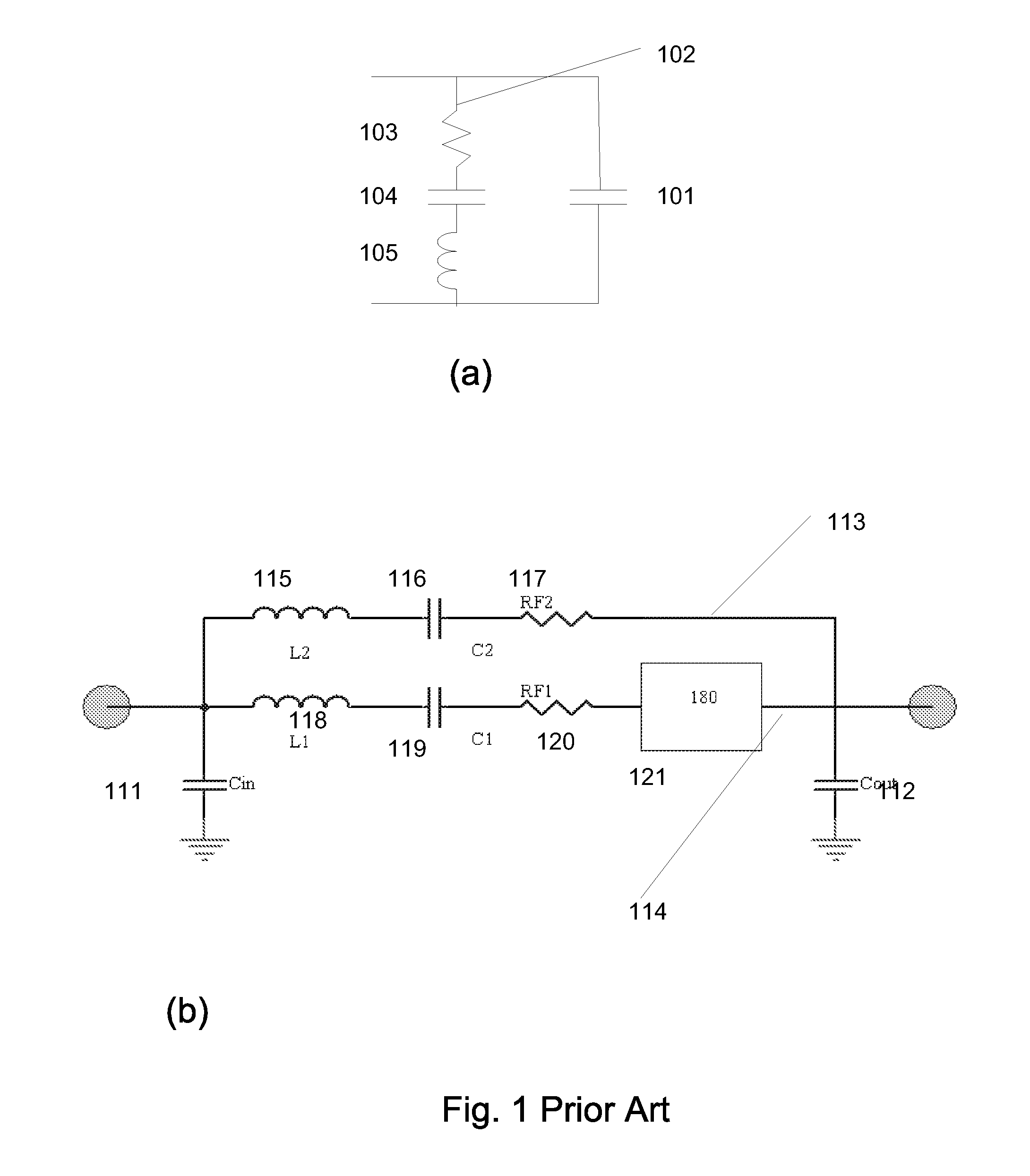
Five significant limitations of the early TSM sensors are (a) the time constant of the static capacitance in parallel with the motional resistance limits measurement range and resolution, (b) the low piezoelectric coupling (k2) of quartz limits measurement range of the motional resistance for a given instrumentation system, (c) Maxwellian properties of real fluids deviate substantially from the Newtonian model above ˜1 MHz for typical hydrocarbons and (d) incidental compressional wave components that are inherent to TSM energy trapping are known to cause an erroneous reading of the viscous losses, and (e) reflections of these compressional waves from an opposing surface establish resonances within the fluid between the crystal face and an adjacent reflective surface.
Performance of the quartz-based MCF structure was still limited by piezoelectric coupling; however the limitation was scaled to higher viscosities by removal of the static capacitance from its previous location in shunt with the motional resonance to be measured.
It is not possible to reliably use this measurement to obtain the differential resistance due to compressional effects 305, 306 or to obtain reliable, repeatable, and accurate viscoelastic effect measurements because of the nonlinearities of the system.
Mode shapes that are not consistent with the one dimensional model will result in very substantial changes of the sensitivity slope itself.
Efforts to separate the relaxation time effects and the compressional radiation effects have been hampered by compressional wave reflections.
The methods offered in the Barlow and Lamb prior art and in the '125 application are limited to the case in which there is no reflection of the compressional mode energy back into the sensor from an opposing surface.
Judicious installation and design of sensor packaging may overcome reflected compressional wave issues to within a reasonable limit of accuracy sufficient for a trending analysis and asset management tool.
However, the miniaturization inherent to increasingly higher operating pressures and the integration of additional sensing structures further complicates the compressional wave effect.
Careful installation and operation of the sensors allows these conditions to be met; however, the attendant restrictions are too burdensome on end users.
It is clear that the prior art method is incapable of tolerating significant degrees of compressional reflection.
While the antireflective fixture measurement 702 of FIG. 7 shows considerably less ripple than the reflective fixture, it is still not a perfect example of anti-reflective fixturing.
However, in any single measurement of the fluid at any given temperature, it is not possible to tell with any degree of certainty whether or not the data is corrupted by the value of the measurement itself.

Method used


Image

  • Controlled compressional wave components of thickness shear mode multi-measurand sensors
  • Controlled compressional wave components of thickness shear mode multi-measurand sensors
  • Controlled compressional wave components of thickness shear mode multi-measurand sensors

Examples


embodiments

[0161]Embodiments demonstrate the integration of conductivity and dielectric electrodes into a viscometer using thickness shear mode coupled resonators. The approaches are generally applicable to any TSM resonator sensor including single pole resonators, multimode resonators, and the like with either thickness field or lateral field excitation. The approach is applicable to linearly polarized resonators as well as planar torsional sensors and the like, as in J. Andle, R. Haskell, M. Chap, and D. Stevens, “Improved Substrate Selection for Lateral Field TSM Sensors”, 2009 IEEE UFFC (unpublished). The well known issues of compressional mode generation are mitigated, and even used to advantage.

[0162]It would be further desired to know the compressional elastic modulus in order to better know density and better correct for errors due to compressional wave radiation. In hydraulic systems, compressibility is of direct interest. Martin, S. J. Martin, G. C. Frye, R. W. Cernosek and S. D. Sen...


PUM

PropertyMeasurementUnit
thicknessaaaaaaaaaa
widthaaaaaaaaaa
lengthaaaaaaaaaa

Abstract

The current invention relates to a conductivity-dielectric (CD) electrode design with apertures that allow compressional waves to propagate away from the surface of the acoustic wave device unimpeded. This prevents reflection of compressional waves that would interact with the viscosity sensor surface, thus altering the device response. It allows compressional waves to pass through, and allows the dual mode viscosity sensor responses to be utilized for density / viscosity / elasticity measurement and correlation. The invention further offers methods of instrumentation to detect unwanted reflections, to compensate, and to correct for the distortions caused by reflections. Finally, the invention provides a system and method for utilizing deliberately introduced reflections to obtain additional information, including fluid density.

Description

[0001]This application claims the benefit of U.S. Provisional Application No. 61 / 243,685 filed Sep. 18, 2009, this application is herein incorporated by reference in its entirety for all purposes; U.S. application Ser. No. 12 / 036,125 filed Feb. 22, 2008 entitled “Sensor, System, and Method for Measuring Fluid Properties Using Multi-Mode Quasi-Shear-Horizontal Resonator”; U.S. application Ser. No. 12 / 540,339 filed Aug. 12, 2009 entitled “Instrumentation of Acoustic Wave Devices”; U.S. application Ser. No. 12 / 780,869 filed May 15, 2010 entitled “Improved Measurement of Fluid Parameters”; U.S. application Ser. No. 12 / 780,868 filed May 15, 2010 entitled “Improved Calibration of High Frequency Fluid Phase Acoustic Sensors”; U.S. application Ser. No. 11 / 814,074 entitled “Electro Acoustic Sensor for High Pressure Environments” to Andle filed Apr. 20, 2006; U.S. application Ser. No. 12 / 202,431 entitled “Asymmetric Composite Acoustic Wave Sensor” to Andle and Haskell filed Sep. 2, 2008; and ...

Claims


Application Information

Patent Timeline
Patent Type & Authority Applications(United States)
IPC IPC(8): G01N11/00G06F19/00G01H13/00
CPCG01N29/036G01N2291/0422G01N29/46G01N29/4418
Inventor ANDLE, JEFFREY C.STEVENS, DANIEL S.HASKELL, REICHL B.TUCKER, DANA Y.G.
Owner MICROSEMI CORP HIGH PERFORMANCE TIMING
Learn More