Communication system and transmitter-receiver for use therewith

a technology of communication system and receiver, which is applied in the direction of power management, multiplex communication, polarisation/directional diversity, etc., and can solve the problem of making the optimal transmitter power as the whole system

Active Publication Date: 2009-07-21
NEC CORP
View PDF8 Cites 7 Cited by
  • Summary
  • Abstract
  • Description
  • Claims
  • Application Information

AI Technical Summary

Benefits of technology

[0012]It is an object of the present invention to provide a communication system and a transmitter-receiver for use therewith in which the power control of the system in the MIMO communication method can be optimally controlled.

Problems solved by technology

If such a general transmitter power control method is directly applied to the MIMO conFIGuration, the power control signal is generated based on the reception power in each receiver, independently, whereby there is a drawback that the optimal transmitter power can be made as the entire system.

Method used


Image

  • Communication system and transmitter-receiver for use therewith
  • Communication system and transmitter-receiver for use therewith
  • Communication system and transmitter-receiver for use therewith

Examples


Embodiment Construction

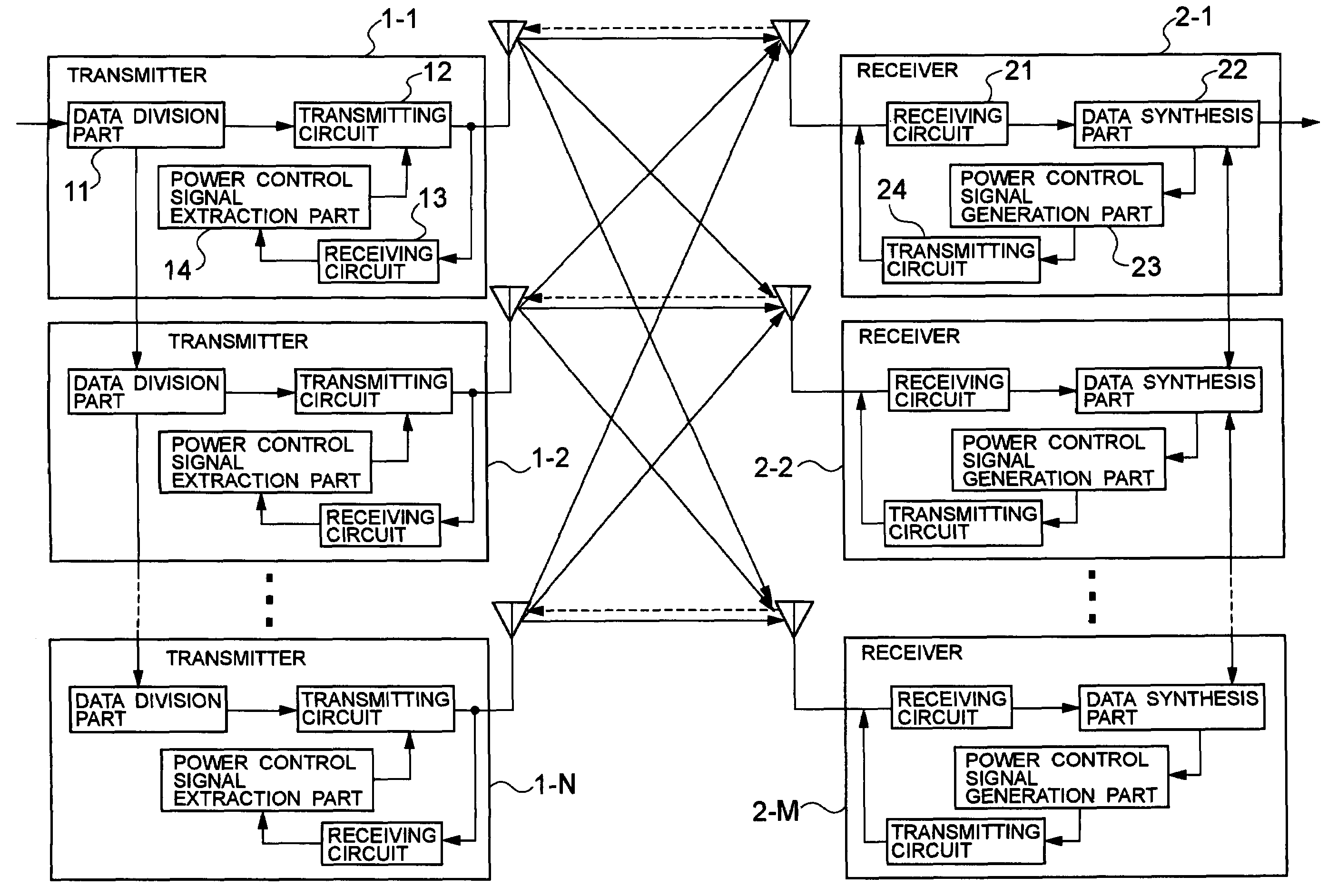
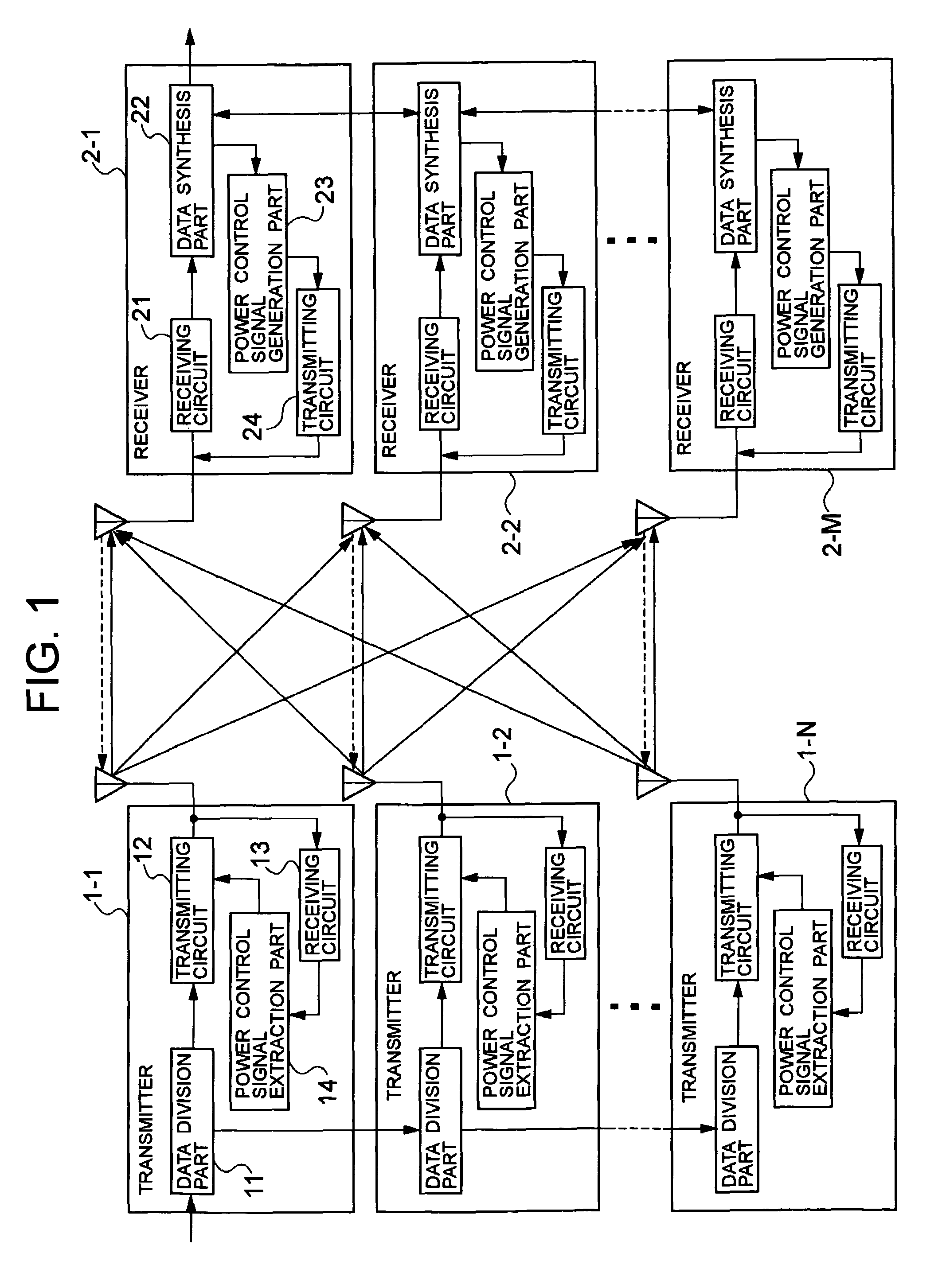
[0023]The embodiments of the present invention will be described below with reference to the drawings. FIG. 1 is a block diagram of a communication system according to an embodiment of the invention. It is supposed that transmitters 1-1 to 1-N and receivers 2-1 to 2-M (M≧N) are independent and individual transmitters and receivers in the normal mode. In making the MIMO communication, an MIMO communication apparatus is constructed by connecting the transmitters 1-1 to 1-N and connecting the receivers 2-1 to 2-M, as shown in FIG. 1.

[0024]In FIG. 1, the same or like parts are designated by the same reference numerals as in FIG. 3. All the transmitters 1-1 to 1-N have the same conFIGuration, and all the receivers 2-1 to 2-M have the same conFIGuration.

[0025]Referring to FIG. 1, the transmission data inputted into the transmitter 1-1 is firstly divided by a data division part 11, one of the data being transmitted from an antenna via a transmitting circuit 12, and the other being outputte...


PUM


Abstract

To achieve the optimal power control of a system in an MIMO communication method.When decoding in accordance with a receiving algorithm of the MIMO communication method in plural receivers, each receiver acquires the reception power level of a received signal from a transmitter paired with the receiver, and generates a transmitter power control signal based on a comparison result of comparing the reception power with a predetermined value. For example, if the reception power level is lower than the predetermined value, a transmitter power control signal of instructing to increase the transmitter power is generated, or otherwise, a transmitter power control signal of instructing to decrease the transmitter power is generated. The generated control signal is transmitted from the receiver to the transmitter paired with the receiver. Each transmitter controls the transmitter power in accordance with the received control signal.

Description

BACKGROUND OF THE INVENTION[0001]1. Field of the Invention[0002]The present invention relates to a communication system and a transmitter-receiver for use therewith, and more particularly to power control in an MIMO (Multiple Input Multiple Output) communication method.[0003]2. Related Art[0004]In a personal radio communication system, the higher communication rate has been achieved owing to the broadband. One of the techniques is a method called an MIMO (refer to Japanese Patent Laid-Open No. 2003-348057). In the MIMO communication method, each of a transmitter 1 and a receiver 2 is provided with a plurality of antennas, in which high speed data to be transmitted is divided into N and transmitted via respective antennas on the transmitter 1, and the transmitted data is restored by making a predetermined signal processing for the signals received by M (M≧N) antennas on the receiver 2, as shown in FIG. 3.[0005]That is, in the transmitter 1, the data to be transmitted is divided into ...

Claims


Application Information

Patent Timeline
Patent Type & Authority Patents(United States)
IPC IPC(8): H04K1/10H04L1/02H04B7/04H04J99/00H04W16/28H04W52/04H04W52/24
CPCH04B7/0426H04W52/42H04L1/203H04B7/005H04B7/15H04J13/00H04J99/00
Inventor IWASAKI, MOTOYA
Owner NEC CORP
Why Eureka
Try Eureka