Dual-charged internal combustion engine and method for operating the same

Inactive Publication Date: 2010-10-12
VOLKSWAGEN AG
View PDF35 Cites 6 Cited by
  • Summary
  • Abstract
  • Description
  • Claims
  • Application Information

AI Technical Summary

Benefits of technology

[0008]This has the advantage that, due to the special arrangement of the superchargers in the air path to the intake pipe and the incorporation of the charge cooler in the intake pipe, an otherwise necessary throttle valve can be eliminated, and at the same time a very small volume is present between the mechanically driven supercharger and the combustion chamber, so that there is a significant improvement in the dynamic behavior.
[0009]It is advantageous for the on-off butterfly valve to be designed in such a way that, in the completely closed state, it essentially seals the air path to the suction intake of the mechanically driven supercharger against a secondary air flow through the mechanically driven supercharger.
[0011]This has the advantage that the load control butterfly valve mounted in the intake / charge cooler module has a dual function, namely, on the one hand, it has the function of a conventional throttle valve in those operating states in which the exhaust gas turbocharger can make available the torque demanded of the internal combustion engine, and, on the other had, it has the function of a recirculated air control valve for a bypass line of the mechanically driven supercharger at high instantaneous torque demands that exceed the capacity of the exhaust gas turbocharger, so that an additional power control element in the air path can be dispensed with.

Problems solved by technology

As long as the exhaust gas turbocharger does not deliver sufficient charge air due to the engine speed being too low, i.e., during start-up and in the low engine speed range, the internal combustion engine is supercharged by the mechanical compressor.

Method used


Image

  • Dual-charged internal combustion engine and method for operating the same
  • Dual-charged internal combustion engine and method for operating the same
  • Dual-charged internal combustion engine and method for operating the same

Examples


Embodiment Construction

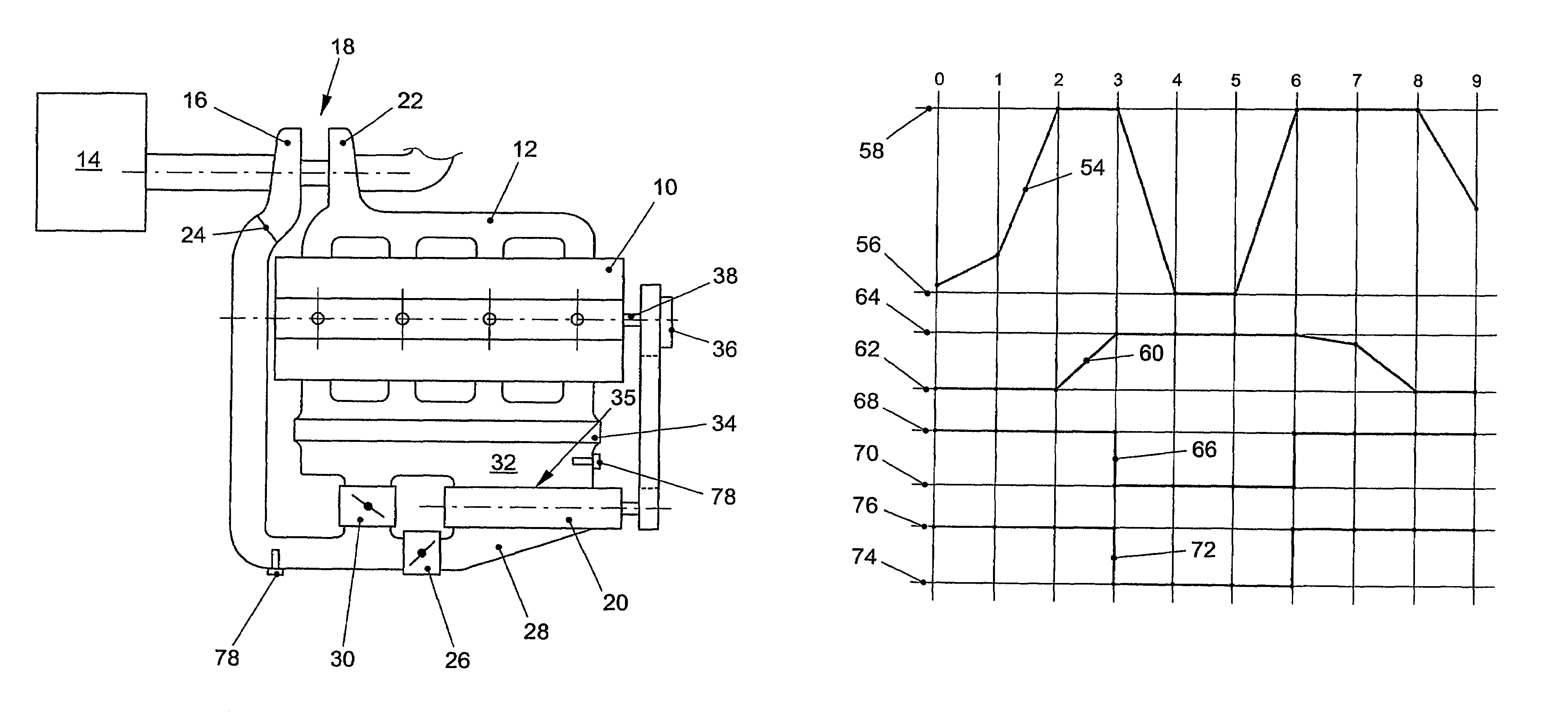
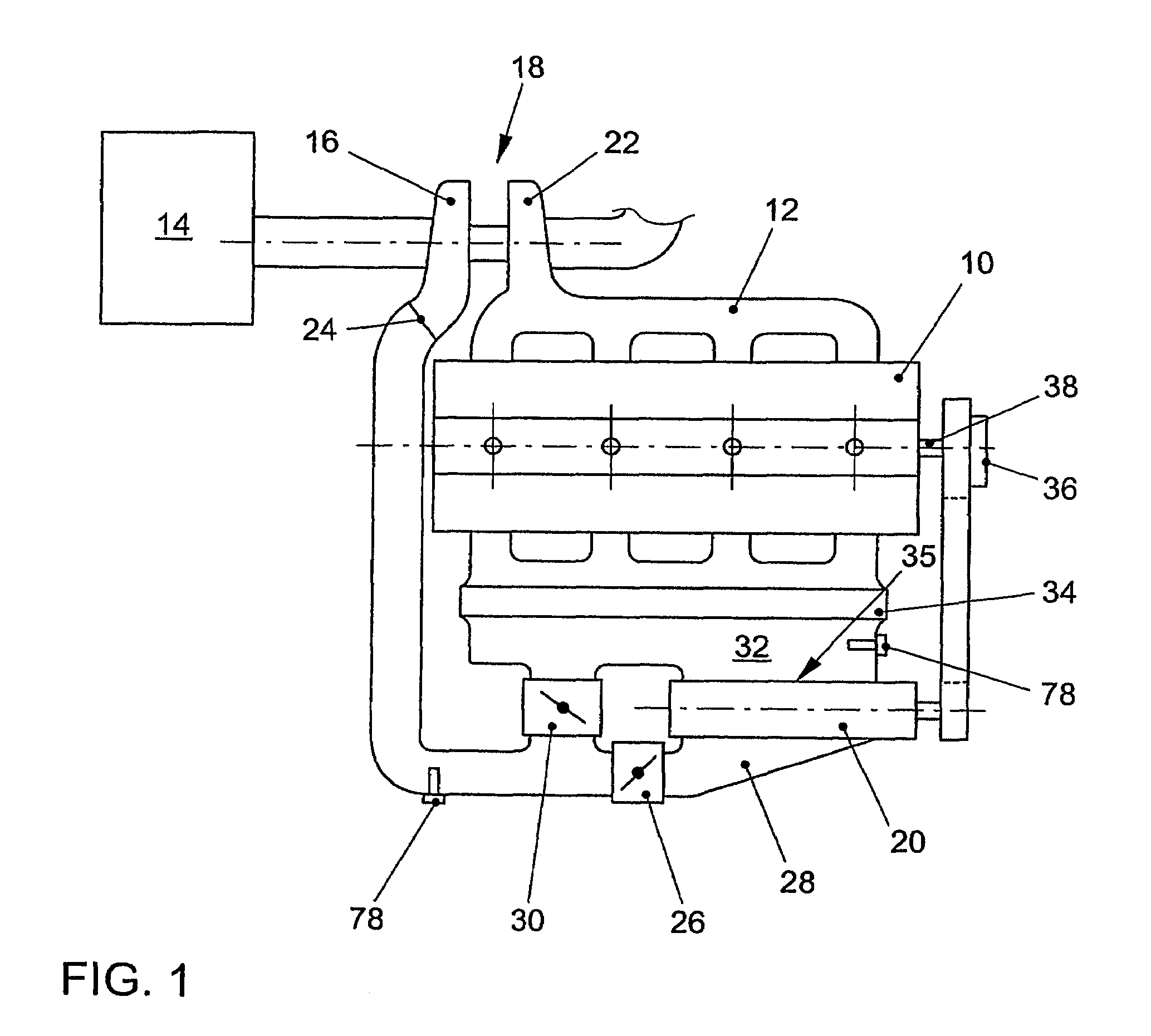
[0017]FIG. 1 shows a preferred embodiment of an internal combustion engine of the invention. It comprises an engine block 10, an exhaust system 12, and an air path for the intake of combustion air or fresh air. The following are mounted in the air path: an air filter 14, a compressor 16 of an exhaust gas turbocharger 18, and a mechanically driven supercharger 20, for example, a compressor. A turbine 22 of the exhaust gas turbocharger 18 is installed in the exhaust system 12 of the internal combustion engine. A pressure outlet 24 of the exhaust gas turbocharger 18 is connected with a suction intake 28 of the mechanically driven supercharger 20 via an on-off butterfly valve 26. Upstream of the on-off butterfly valve 26, the pressure outlet 24 of the exhaust gas turbocharger 18 is connected with an intake pipe 32 via a load control butterfly valve 30. In addition, a charge cooler 34 is provided, which is integrated in the intake pipe. The charge cooler 34 and intake pipe 32 together fo...


PUM


Abstract

The invention relates to an internal combustion engine, especially of a motor vehicle, which comprises an air path for intake air in which a mechanically driven charge unit (20), especially a compressor, which can be connected and disconnected by means of a coupling (36), an exhaust gas turbocharger (18), an intake pipe (32), connected to air inlets of a cylinder block (10) of the internal combustion engine, and a charge cooler (34) are mounted. One pressure outlet (35) of the mechanically driven charge unit (20 is directly connected to the intake pipe (32) and one pressure outlet (24) of the exhaust gas charger (18) is connected to an intake inlet (28) of the mechanically driven charge unit (20). The pressure outlet (24) of the exhaust gas charger (18) is connected to the intake inlet (28) of the mechanically driven charge unit (20) via an on-off butterfly valve (26) and upstream of said on-off butterfly valve (26) to the intake pipe (32) via a load butterfly valve (30). The charge cooler (34) is integrated into the intake pipe (32) to give an intake / charge cooler module.

Description

[0001]This is a U.S. national stage of application No. PCT / EP2005 / 013730, filed on Dec. 20, 2005. Priority is claimed on that application and on the following application:[0002]Country: Germany, Application No.: DE 10 2005 004 122.1 Filed: Jan. 28, 2005BACKGROUND OF THE INVENTION[0003]The invention concerns an internal combustion engine, especially of a motor vehicle, with an air path for intake air, in which are installed a mechanically driven supercharger, especially a compressor, which can be connected and disconnected by means of a coupling; an exhaust gas turbocharger; an intake pipe connected with the air intakes of a cylinder block of the internal combustion engine; and a charge air cooler. A pressure outlet of the mechanically driven supercharger is directly connected to the intake pipe, and a pressure outlet of the exhaust gas turbocharger is connected to a suction intake of the mechanically driven supercharger. The invention also concerns a method for operating this intern...

Claims


Application Information

Patent Timeline
Patent Type & Authority Patents(United States)
IPC IPC(8): F02B33/44F02B29/04F02B37/04F02B33/00
CPCF02B37/04F02B37/14F02B37/16F02B29/0475Y02T10/144Y02T10/12
Inventor NOODT, FLORIANSCHWEIZER, MARC-JOCHENKLOFT, MANFRED
Owner VOLKSWAGEN AG
Why Eureka
Try Eureka