Ballast for a gas discharge lamp and a method of controlling this ballast

a technology for gas discharge lamps and ballasts, which is applied in the direction of electric variable regulation, process and machine control, instruments, etc., can solve the problems of high form factor and relatively complex design and manufacture of such transformers, and achieve the effect of reducing the capacitance of large capacitors and increasing power control

Inactive Publication Date: 2008-11-11
VALEO VISION SA
View PDF5 Cites 7 Cited by
  • Summary
  • Abstract
  • Description
  • Claims
  • Application Information

AI Technical Summary

Benefits of technology

[0035]In addition, the invention, because of the availability of control signals representing operating phases of the discharge lamp, also has the corresponding advantage of allowing an increased power control during the starting of the lamp. For example, by forcing the control signals supplied to the DC to DC converter to one or more predetermined duty cycles during the starting phase. It thus becomes possible to reduce the capacitance of large capacitors normally used for supplying the current necessary at the time of starting of the lamp.

Problems solved by technology

However, the design and manufacture of such a transformer are relatively complex since the voltages and currents involved are high.
In addition, the presence of the two windings and of their connection terminals necessarily results in a high form factor.

Method used


Image

  • Ballast for a gas discharge lamp and a method of controlling this ballast
  • Ballast for a gas discharge lamp and a method of controlling this ballast
  • Ballast for a gas discharge lamp and a method of controlling this ballast

Examples


Embodiment Construction

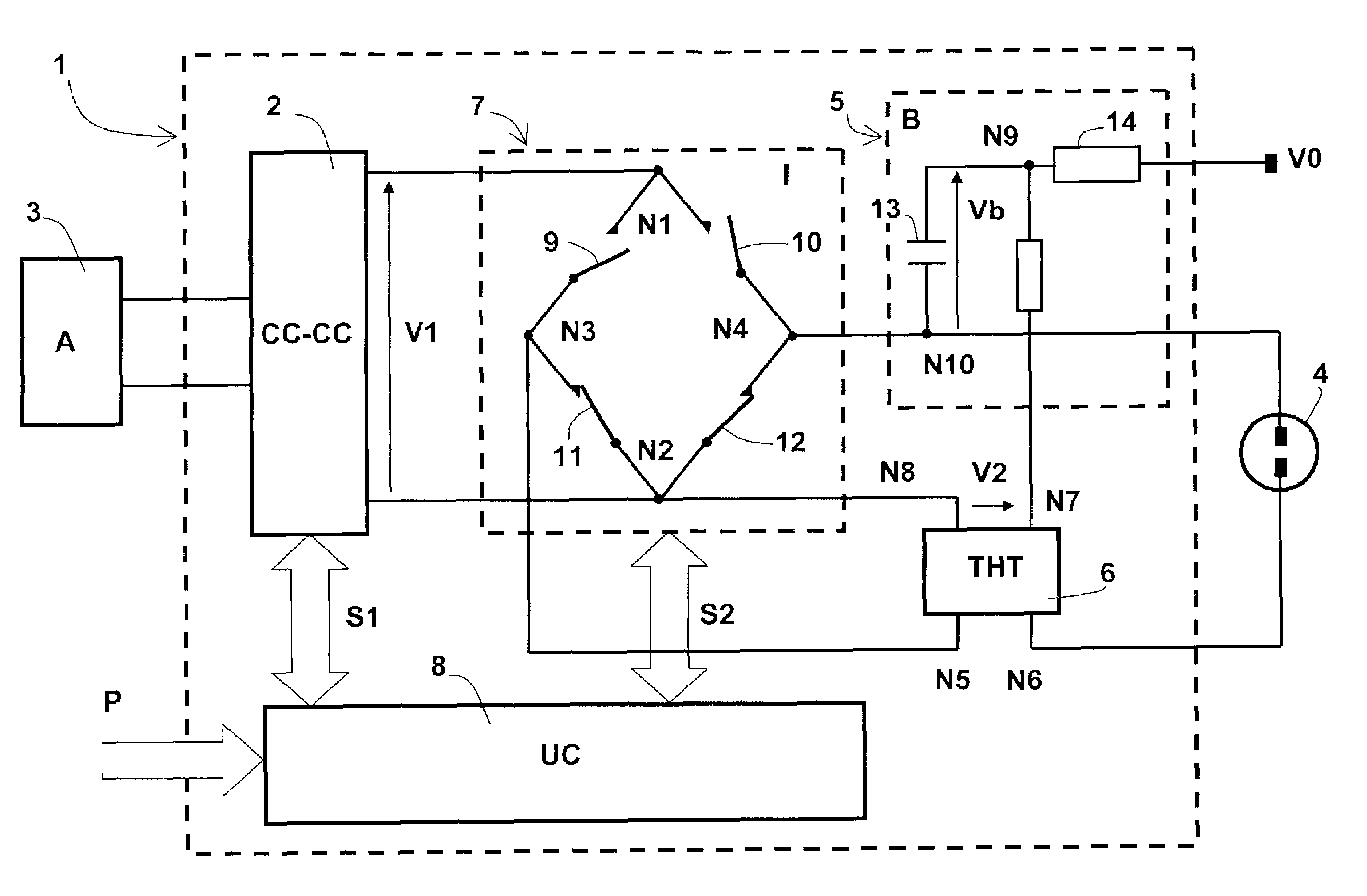
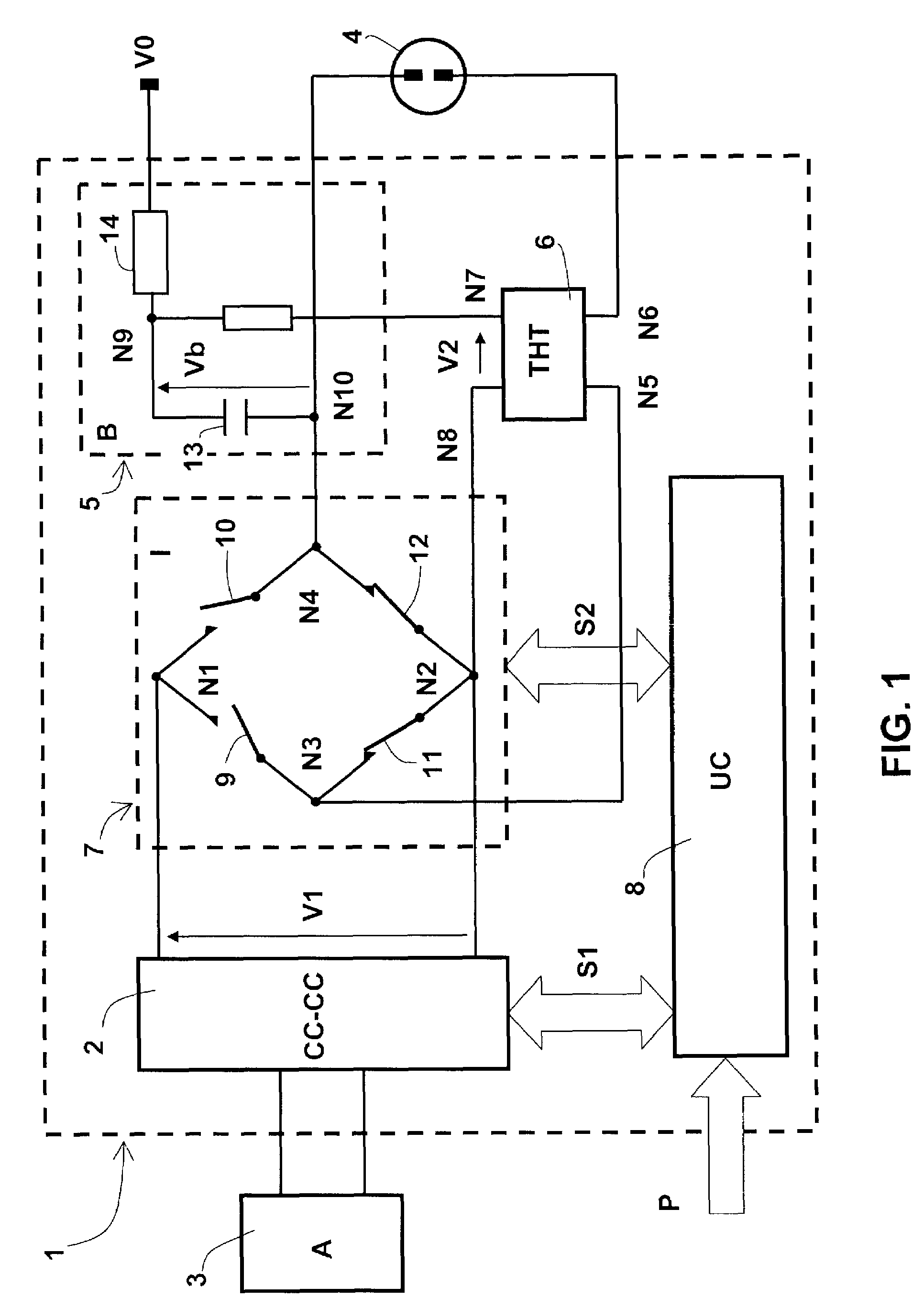
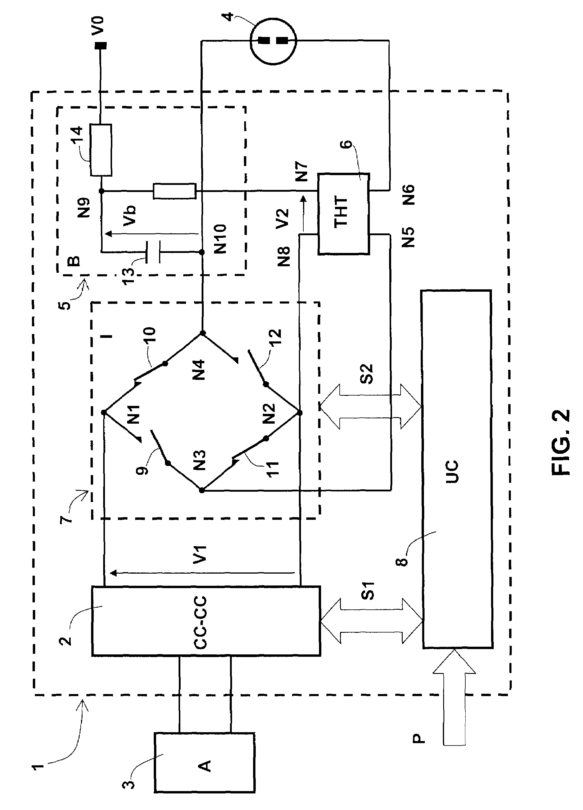
[0040]The functional architecture of the ballast according to the invention is depicted in FIGS. 1 and 2.

[0041]The ballast 1 comprises essentially a DC to DC converter 2 with chopping supplied by a 12 V DC supply source 3 and supplying a DC high voltage V1 of around 450 V, from which there are produced the various voltages necessary for the discharge lamp 4 to start and operate in continuous regime.

[0042]The discharge lamp 4 is a high-intensity xenon gas discharge lamp that requires in particular an ignition voltage of around 25 kV. This very high voltage is produced from the DC high voltage V1 by a voltage step-up circuit 5 supplying, at a voltage difference V2 of around 1000 V, a dedicated ignition voltage generator 6 when the ignition phase is initiated.

[0043]The AC high voltage necessary for the functioning of the discharge lamp 4 in continuous regime is produced in a manner known per se by means of a DC to AC converter, consisting of an inverter bridge 7, from the DC high volta...


PUM


Abstract

A ballast that comprises a DC-DC converter, a DC-AC converter, a lighting voltage generator and a control unit. A difference in voltage between input terminals of the lighting voltage generator is generated by a voltage step-up circuit of the “self-boosting” type from a DC voltage supplied by the DC-DC converter and an auxiliary voltage source V0. The ballast makes it possible to obtain a voltage level V2 that is equal to twice a first voltage level V1 increased by the auxiliary voltage V0.

Description

TECHNICAL FIELD OF THE INVENTION[0001]The present invention concerns a ballast for a gas discharge lamp, in particular a xenon lamp, and a method of controlling this ballast, in particular during the initiation of the phase of switching on the lamp.TECHNOLOGICAL BACKGROUND OF THE INVENTION[0002]For the purpose of improving both the light power and the energy efficiency of light sources used in many fields, such as vehicle headlights or video projectors, current technical changes are leading to replacing filament lamps with high-intensity gas discharge lamps. Unlike conventional bulbs, which were designed to be connected directly to a low-voltage source, such as the battery of a vehicle, or a medium voltage, such as the domestic mains at 110 or 220 V, these new lamps require high voltages, AC or DC, according to the operating mode, in order to create and maintain the electrical discharge in the gas.[0003]In the automotive field, these high voltages, specific to each type of lamp (aro...

Claims


Application Information

Patent Timeline
Patent Type & Authority Patents(United States)
IPC IPC(8): G06F1/00
CPCH05B41/2881Y02B20/204Y02B20/00
Inventor NICOLAI, JEAN-MARC
Owner VALEO VISION SA
Why Eureka
Try Eureka