Wire bonding apparatus

a technology of wire bonding and wire, which is applied in the direction of soldering apparatus, manufacturing tools,auxillary welding devices, etc., can solve the problems of inferior maintenance characteristics and achieve the effect of improving the maintenance characteristics of the bonding arm

Inactive Publication Date: 2009-07-28
SHINKAWA CO LTD
View PDF8 Cites 2 Cited by
  • Summary
  • Abstract
  • Description
  • Claims
  • Application Information

AI Technical Summary

Benefits of technology

[0006]Accordingly, the object of the present invention is to provide a wire bonding apparatus in which a preparatory pressure adjustment of the piezoelectric element and a replacement of the piezoelectric element are performed without removing the bonding arm from the wire bonding apparatus, thus improving the maintenance characteristics of the bonding arm.
[0017]In the present invention, the preparatory pressure application means is comprised of an external operating portion that is operable from the outside of the bonding arm and a conversion portion that converts the movement of this external operating portion into a movement in the axial direction of the bonding arm and applies a preparatory pressure to the piezoelectric element. Accordingly, a preparatory pressure can be applied to the piezoelectric element by operating the external operating portion disposed outside of the bonding arm. More specifically, the preparatory pressure can be adjusted without removing the bonding arm from the bonding apparatus. Furthermore, in cases where the piezoelectric element is to be replaced, such replacing can be accomplished without removing the bonding arm from the bonding apparatus. Thus, in the present invention, the maintenance characteristics of the bonding arm are high.

Problems solved by technology

In the above-described prior art, the preparatory pressure bolt that applies a preparatory pressure is provided on the axial line of the bonding arm on the rear portion of or behind the piezoelectric element; accordingly, adjustment of the preparatory pressure and replacement of the piezoelectric element cannot be performed unless the bonding arm is removed from the bonding apparatus, which is inconvenient and leads to the problem of inferior maintenance characteristics.

Method used


Image

  • Wire bonding apparatus
  • Wire bonding apparatus
  • Wire bonding apparatus

Examples


first embodiment

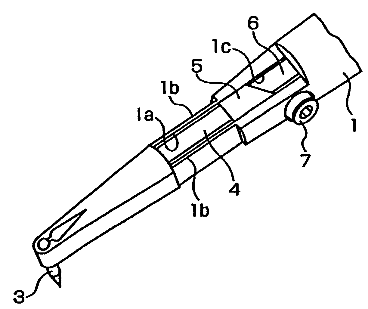
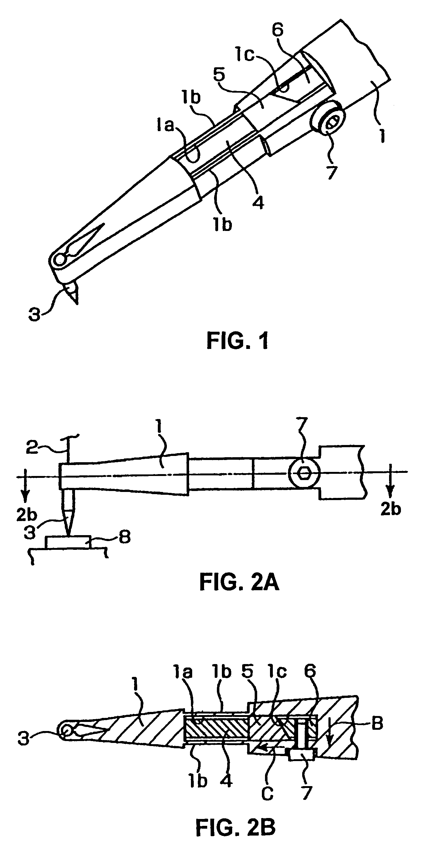
[0023]the wire bonding apparatus of the present invention will be described with reference to FIGS. 1, 2A and 2B.

[0024]A capillary 3 through which a wire 2 is passed is fastened to the tip end of the bonding arm 1.

[0025]A piezoelectric element opening 1a is formed in the bonding arm 1 so that the piezoelectric element opening 1a is in the vicinity of the attachment portion of the capillary 3. Both side portions of the piezoelectric element opening 1a are elastic portions 1b made of thin elements. In addition, an attachment base opening 1c is formed on the rear part of or behind the piezoelectric element opening 1a (i.e., on the right side in FIG. 2B).

[0026]A piezoelectric element 4 is provided inside the piezoelectric element opening 1a, and two wedge-form attachment bases, a front wedge-form attachment base 5 and a rear wedge-form attachment base 6 are provided inside the attachment base opening 1c.

[0027]So as to hold the piezoelectric element 4 and front and rear wedge-form attac...

second embodiment

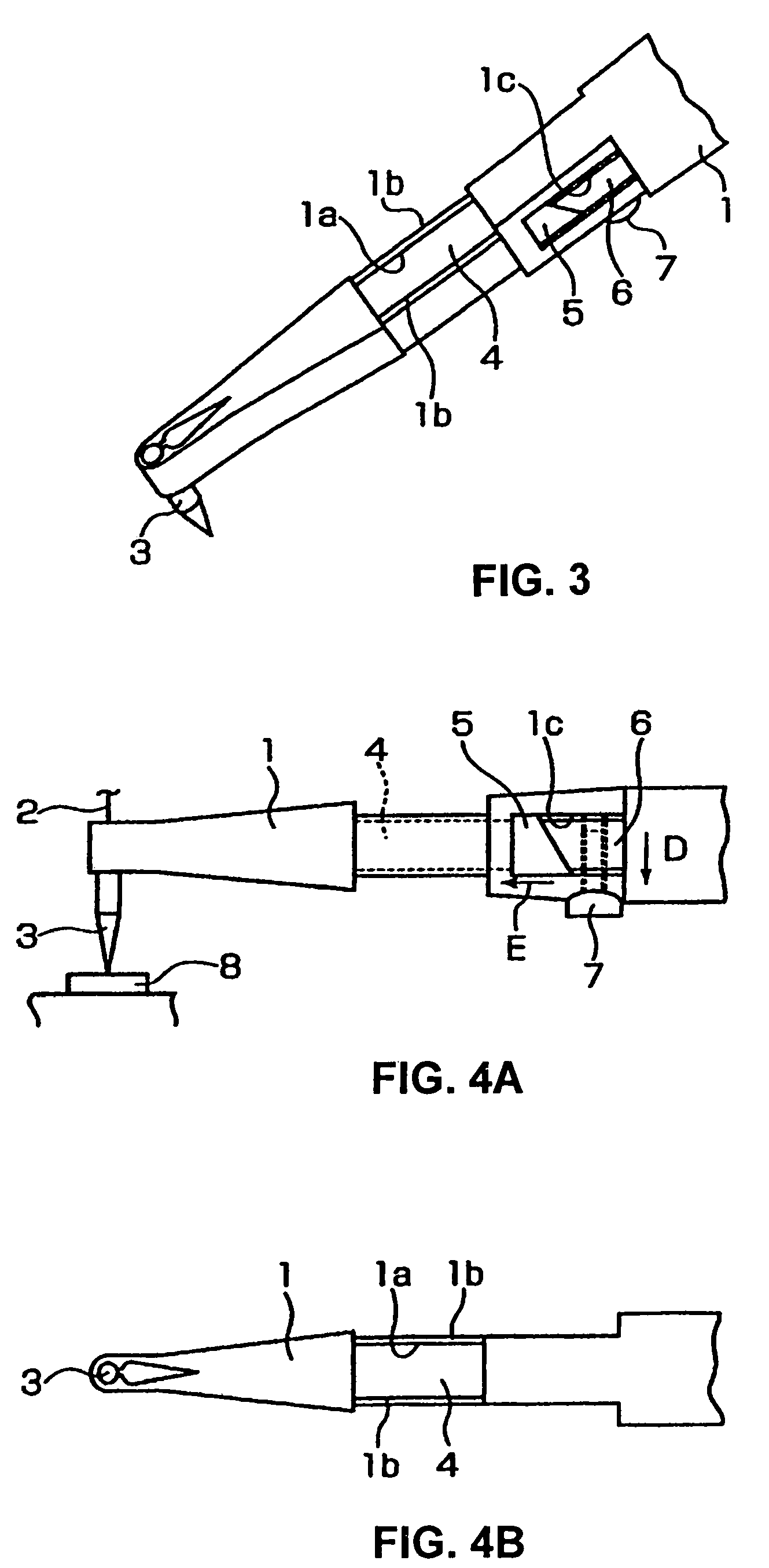
[0036]Accordingly, in the structure of the second embodiment, when the preparatory pressure bolt 7 is screwed in, the rear wedge-form attachment base 6 is moved in the direction of or toward the preparatory pressure bolt 7 (the direction of arrow D). Since the contact surfaces of the front and rear wedge-form attachment bases 5 and 6 have a wedge shape, the front wedge-form attachment base 5 is moved in the direction of or toward the capillary 3 (the direction of arrow E). As a result, a preparatory pressure is applied to the piezoelectric element 4.

[0037]Thus, since the preparatory pressure bolt 7 is disposed on the undersurface of the bonding arm 1, the preparatory pressure can be adjusted by merely turning the preparatory pressure bolt 7 without removing the bonding arm 1 from the apparatus. Furthermore, in cases where the piezoelectric element 4 is to be replaced, such a replacement can be done by merely removing the preparatory pressure bolt 7 from the bonding arm 1 without rem...

third embodiment

[0038]the present invention will be described with reference to FIGS. 5A and 5B.

[0039]In this third embodiment, an eccentric pin 10 is used instead of the wedge-form attachment bases 5 and 6 and preparatory pressure bolt 7 of the respective embodiments described above. More specifically, a piezoelectric element 4 and the rising portion 111a of an L-shaped attachment base 11 are provided inside the piezoelectric element opening 1a, and the horizontal surface portion 11b of the attachment base 11 is disposed on the undersurface of the bonding arm 1.

[0040]The attachment base 11 is fastened to the bonding arm 1 by a fastening screw 12, and a hole 11c that is larger than the screw portion of the fastening screw 12 is formed in the fastening screw portion of the attachment base 11 so that the attachment base 11 is movable in the axial direction of the bonding arm 1.

[0041]The shaft portion 10a of the eccentric pin 10 is supported on the bonding arm 1 in a rotatable fashion, and an operatin...


PUM

PropertyMeasurementUnit
pressureaaaaaaaaaa
preparatory pressureaaaaaaaaaa
piezoelectricaaaaaaaaaa

Abstract

In an bonding apparatus, a piezoelectric element 4 being built into the vicinity of the capillary attachment portion of a bonding arm 1 so that the capillary 3 can be caused to vibrate in the axial direction of the bonding arm 1. The preparatory pressure application device that applies a preparatory pressure to the piezoelectric element 4 includes two wedge-form attachment bases 5 and 6 which are disposed to the rear of or behind the piezoelectric element 4, and a preparatory pressure bolt 7 which is screwed into the wedge-form attachment base 6 from the outside of the bonding arm 1; and a preparatory pressure is applied to the piezoelectric element 4 by the movement of the wedge-form attachment base 5 in the axial direction of the bonding arm 1 caused by the rotation of the preparatory pressure bolt 7.

Description

BACKGROUND OF THE INVENTION[0001]1. Technical Field[0002]The present invention relates to a wire bonding apparatus that performs bonding while causing the capillary to vibrate by means of a piezoelectric element.[0003]2. Description of the Related Art[0004]Japanese Patent No. 3245445 (Japanese Patent Application Laid-Open (Kokai) No. H5-275502) discloses an example of a wire bonding apparatus that causes a capillary to vibrate by means of a piezoelectric element. In this prior art, a piezoelectric element is incorporated in the vicinity of the capillary attachment portion of the bonding arm so that the capillary vibrates in the axial direction of the bonding arm. In the bonding arm, a preparatory pressure bolt that applies a preparatory pressure to the piezoelectric element is installed on the axial line of the bonding arm in the rear portion of or behind the piezoelectric element.[0005]In the above-described prior art, the preparatory pressure bolt that applies a preparatory pressu...

Claims


Application Information

Patent Timeline
Patent Type & Authority Patents(United States)
IPC IPC(8): B23K20/10B23K1/06H01L21/60B23K20/00B23K37/00H01L21/607H01L41/09H02N2/00
CPCB23K20/005B23K20/106H01L24/78H01L2224/78301H01L2924/01005H01L2924/00014H01L2924/01006H01L2924/01033H01L2224/48H01L2224/45099
Inventor KONDO, YUTAKA
Owner SHINKAWA CO LTD
Why Eureka
Try Eureka