Headlight, taillight and streetlight detection

a technology of headlights and streetlights, applied in the field of vehicle control systems, can solve the problems of affecting the maintenance time affecting the performance of the other control system,

Active Publication Date: 2009-07-28
MOBILEYE VISION TECH LTD
View PDF17 Cites 207 Cited by
  • Summary
  • Abstract
  • Description
  • Claims
  • Application Information

AI Technical Summary

Problems solved by technology

Vehicle control systems, such as disclosed in U.S. Pat. No. 6,831,261 which rely on changing exposure parameters (ie, aperture, exposure, magnification, etc) in order to detect headlights have a difficult time maintaining other control systems which rely on the same camera, e.g. Lane Departure Warning, Forward Collision Warning, etc.
As a result of changing exposure parameters half or more of the (possibly critical) frames may not be available for the other control systems.
This greatly affects performance of the other control systems.
Additionally, the use of color cameras with infrared filters required to achieve good spectral separation reduces imaging sensitivity by a factor of six or more.
A reduction in sensitivity by such a factor has an adverse impact on other vehicle control application such as LDW performance in dark scenes.
The presence of an infrared filter also negates the use of the camera as a near infrared sensor for applications, such as pedestrian detection.
Thus, headlight control systems which make strong use of color or spectral analysis in the captured images (such as in U.S. Pat. No. 6,831,261) will tend not be compatible with other applications without sacrificing performance.

Method used


Image

  • Headlight, taillight and streetlight detection
  • Headlight, taillight and streetlight detection
  • Headlight, taillight and streetlight detection

Examples


Embodiment Construction

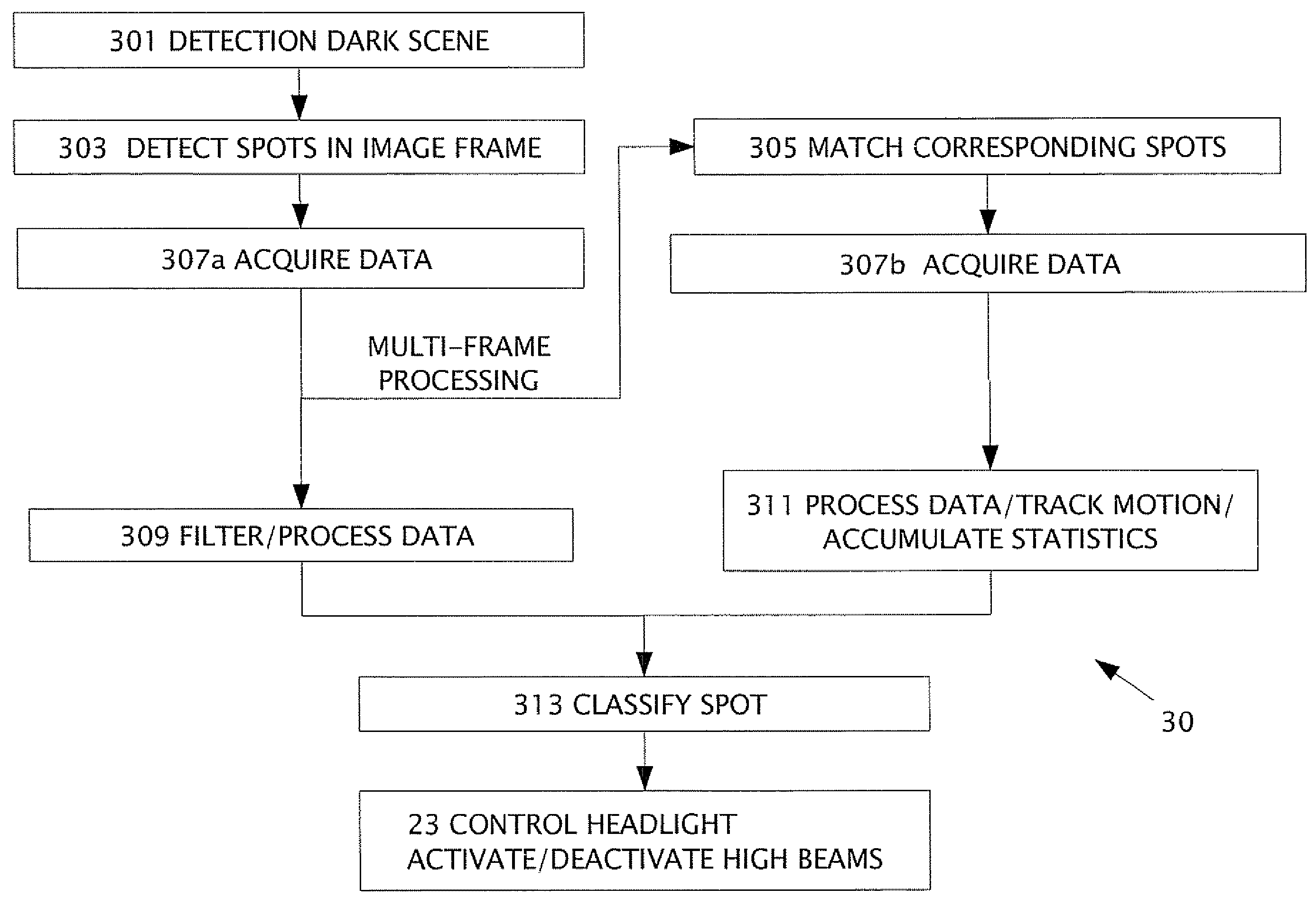
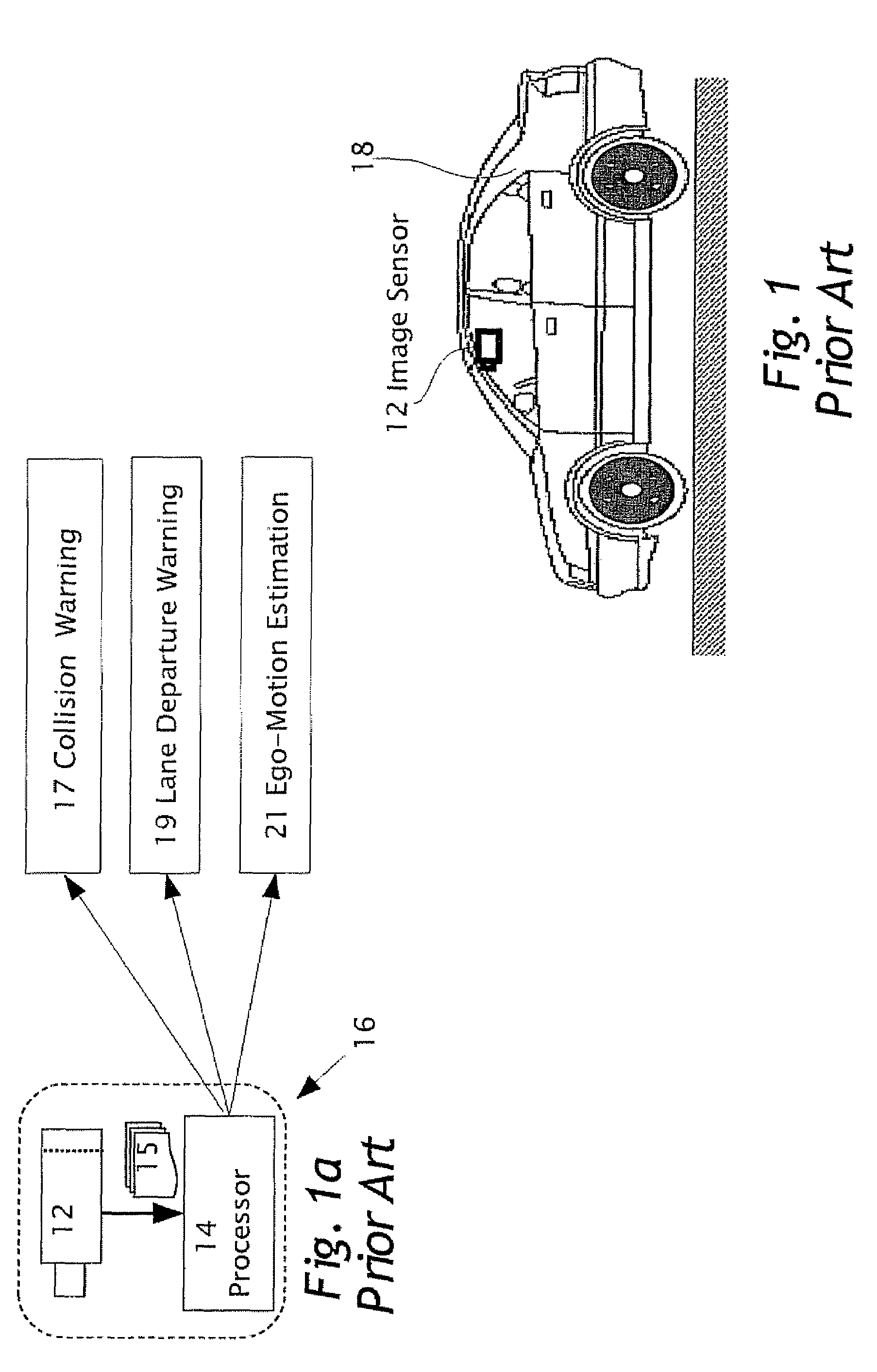
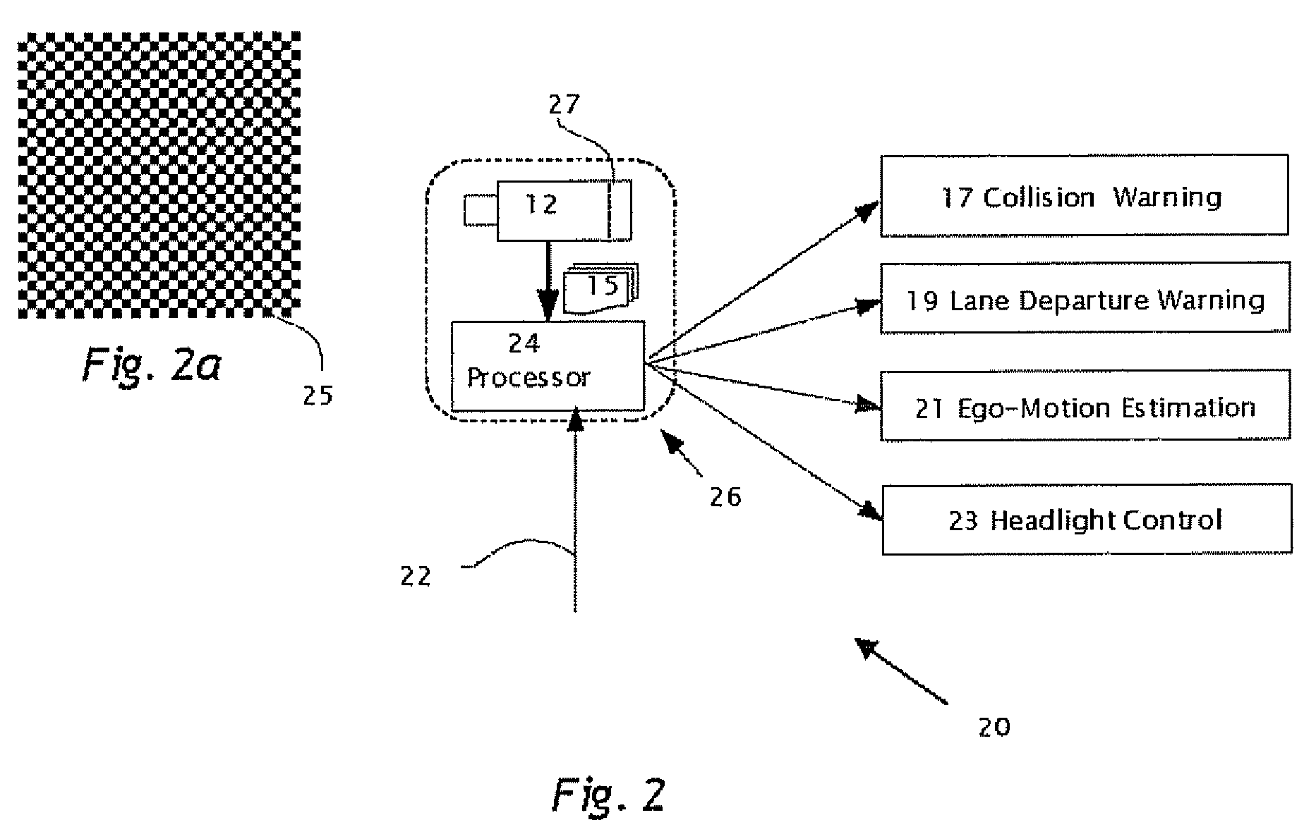
[0034]The present invention is of a system and method for detecting and classifying objects in real time, e.g. oncoming vehicle headlights, leading vehicle taillights and streetlights, in a series of image frames 15 obtained from a camera mounted on an automobile to provide a signal for switching the headlights between high beams and low beams, specifically with image frames 15 available for use by other vehicle control applications

[0035]The principles and operation of a system and method of detecting and classifying objects in real time, in a series of images obtained from a camera mounted on an automobile to provide a signal for switching the headlights between high beams and low beams, according to the present invention, may be better understood with reference to the drawings and the accompanying description.

[0036]Before explaining embodiments of the invention in detail, it is to be understood that the invention is not limited in its application to the details of design and the a...


PUM


Abstract

A method in a computerized system including an image sensor mounted in a moving vehicle. The image sensor captures image frames consecutively in real time. In one of the image flames, a spot is detected of measurable brightness; the spot is matched in subsequent image frames. The image frames are available for sharing between the computerized system and another vehicle control system. The spot and the corresponding spot are images of the same object. The object is typically one or more of headlights from an oncoming vehicle, taillights of a leading vehicle, streetlights, street signs and / or traffic signs. Data is acquired from the spot and from the corresponding spot. By processing the data, the object (or spot) is classified. producing an object classification. The vehicle control system controls preferably headlights of the moving vehicle based on the object classification. The other vehicle control system using the image frames is one or more of: lane departure warning system, collision warning system and / or ego-motion estimation system.

Description

CROSS REFERENCE TO RELATED APPLICATIONS[0001]The present application claims the benefit under 35 USC 119(e) of U.S. provisional application 60 / 785,351 filed on Mar. 24, 2006, and 60 / 836,670 filed Aug. 10, 2006, the disclosures of which are incorporated herein by reference.FIELD AND BACKGROUND OF THE INVENTION[0002]The present invention relates to vehicle control systems in vehicles, Specifically, the present invention detects and classifies objects in real time, e.g. oncoming vehicle headlights, leading vehicle taillights and streetlights, in a series of images obtained from a camera mounted on a vehicle, The images are used in parallel by a number of vehicle control systems including lane departure detection, forward collision control and headlight control systems. The classification of objects is preferably used by more than one of the vehicle control systems. In a headlight control system, the classification of objects is used to provide a signal for switching the headlights betw...

Claims


Application Information

Patent Timeline
Patent Type & Authority Patents(United States)
IPC IPC(8): H01L27/00B60Q1/02
CPCB60Q1/143G06K9/00825G06K9/00818G08G1/16G08G1/167B60Q2300/3321B60Q2300/41B60Q2300/42B60Q2300/45G08G1/165G08G1/166G06V20/582G06V20/584
Inventor STEIN, GIDEON P.HADASSI, OFERBEN HAIM, NOAMWOLFOVITZ, URI
Owner MOBILEYE VISION TECH LTD
Why Eureka
Try Eureka